
BEST ACCESS SYSTEMS
Indianapolis, Indiana
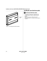
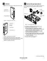
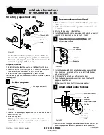
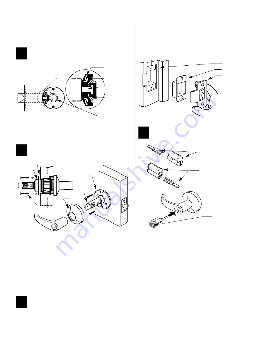
lines up with the hub face (see Figure 40 — blow-up).
Note 1:
Make sure the locking pin locks into the rose liner.
Note 2:
Locksets will fit doors 1 3/4" to 2 1/4" thick. (A spacer is avail-
able for 1 3/8" doors.) See the enlarged view for the correct rose adjust-
ment for these thicknesses.
5
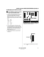
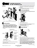
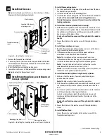
Engage retractor in latch
■
With the latch in place, install the chassis from the outside. Make
sure the latch tabs engage the chassis frame and the latch tailpiece
engages the retractor (see Figure 41).
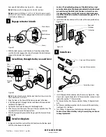
6
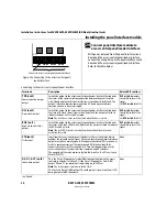
Install liner, through-bolts, rose and lever
Note:
For lead-lined locksets, slide the lead shield (not shown) over the
sleeve and into the 2 1/8" hole.
1 Align the holes in the liner with the holes prepared in the door.
2 Install through-bolts through the liner and door in the top and bot-
tom holes (see Figure 42).
3 Tighten the liner onto the door with the through-bolts.
4 Slide the rose over the sleeve, then press the rose onto the liner. The
rose should fit closely to the door surface.
5 With the lever pointing toward the hinges, push the lever on firmly
until seated.
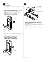
7
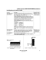
Install strike plate
1 In alignment with the center of the latch bolt, mortise the door jamb
to fit the strike box and strike plate.
Caution:
The deadlocking plunger of the latch bolt must not
enter the strike plate. The plunger deadlocks the latch bolt and
prevents forcing the latch when the door is closed. An exces-
sive gap may reduce security and/or cause a improper opera-
tion of the latch bolt assembly. A maximum door gap of 1/8" is
recommended.
2 Insert the strike box and secure the strike with screws provided (see
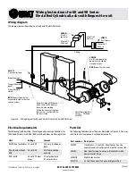
8
Install core
1 Insert the proper throw member into the core (see Figure 44 — top).
Six pin cores require the number “6” throw member; seven pin cores
require the number “7” throw member.
2 Put the control key into the core and turn the key 15 degrees clock-
wise.
3 Put the core and throw member into the lever with the control key
(see Figure 44 — bottom).
4 Turn the key 15 degrees counterclockwise and remove the key.
Caution:
Since the control key is a high-security key, make sure
to keep it protected.
Figure 41
Figure 42
Chassis frame
Latch tabs
Latch tailpiece
Retractor
Chassis
Chassis
Through
Inside liner
Sleeve
Rose
Liner
hub
-bolt
Figure 43
Figure 44
Door jamb
Strike box
Strike plate
BEST
6-pin core & throw member
7-pin core & throw member
Control key in core
T56075/Rev – 1798029 ER-7991-1 Jan 2000
Summary of Contents for 34HW
Page 1: ......
Page 6: ...Contents vi W Series Service Manual...
Page 38: ...IDH Max Locks Functions and Parts 2 24 W Series Service Manual...
Page 54: ...Electrified Locks Functions and Parts 3 16 W Series Service Manual...
Page 140: ...Service and Maintenance for Cylindrical Locks 5 30 W Series Service Manual...
Page 158: ...Additional Service and Maintenance for IDH Max Locks 6 18 W Series Service Manual...
Page 162: ...Glossary A 4 W Series Service Manual...
Page 164: ...Installation Instructions B 2 W Series Service Manual...