Service and Maintenance for Mortise Locks
4–52
W Series Service Manual
4.
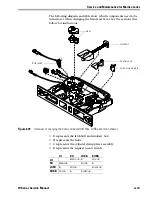
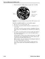
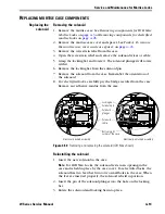
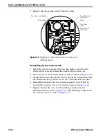
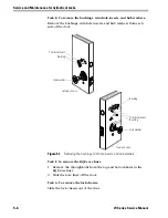
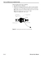
For electrified locks
, place the bridge rectifier in the same position
as the old one and glue it to the case using a gel-type adhesive that
bonds plastic and metal. Hold the bridge rectifier in position for one
minute to allow the adhesive to cure.
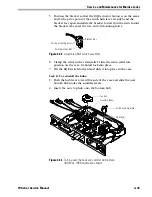
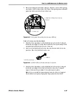
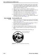
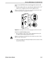
5. Make sure that the solenoid wires or cable is not pinched.
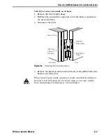
6. Clamp the solenoid wires or cable in the strain relief. Slide the strain
relief into position on the case. It should lock into place.
7. Reinstall the mortise case cover and case spacer. See
reinstall the mortise case cover and case spacer:
8. Reinstall the mortise case. See
Replacing the RQE
switch
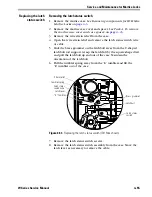
Removing the RQE switch
1. Remove the mortise case. See
Removing components for IDH Max
Removing components for electrified
.
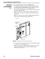
2. Remove the mortise case cover and spacer. See
the mortise case cover and case spacer:
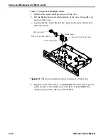
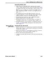
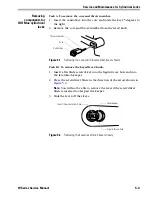
3. Remove the wire strain relief from the case.
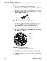
4. Open the wire strain relief and remove the RQE wires or cable.
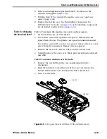
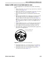
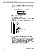
5. Remove the hubs from the case. Maintain the orientation of the
hubs.
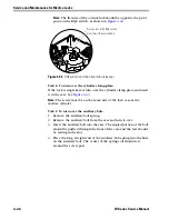
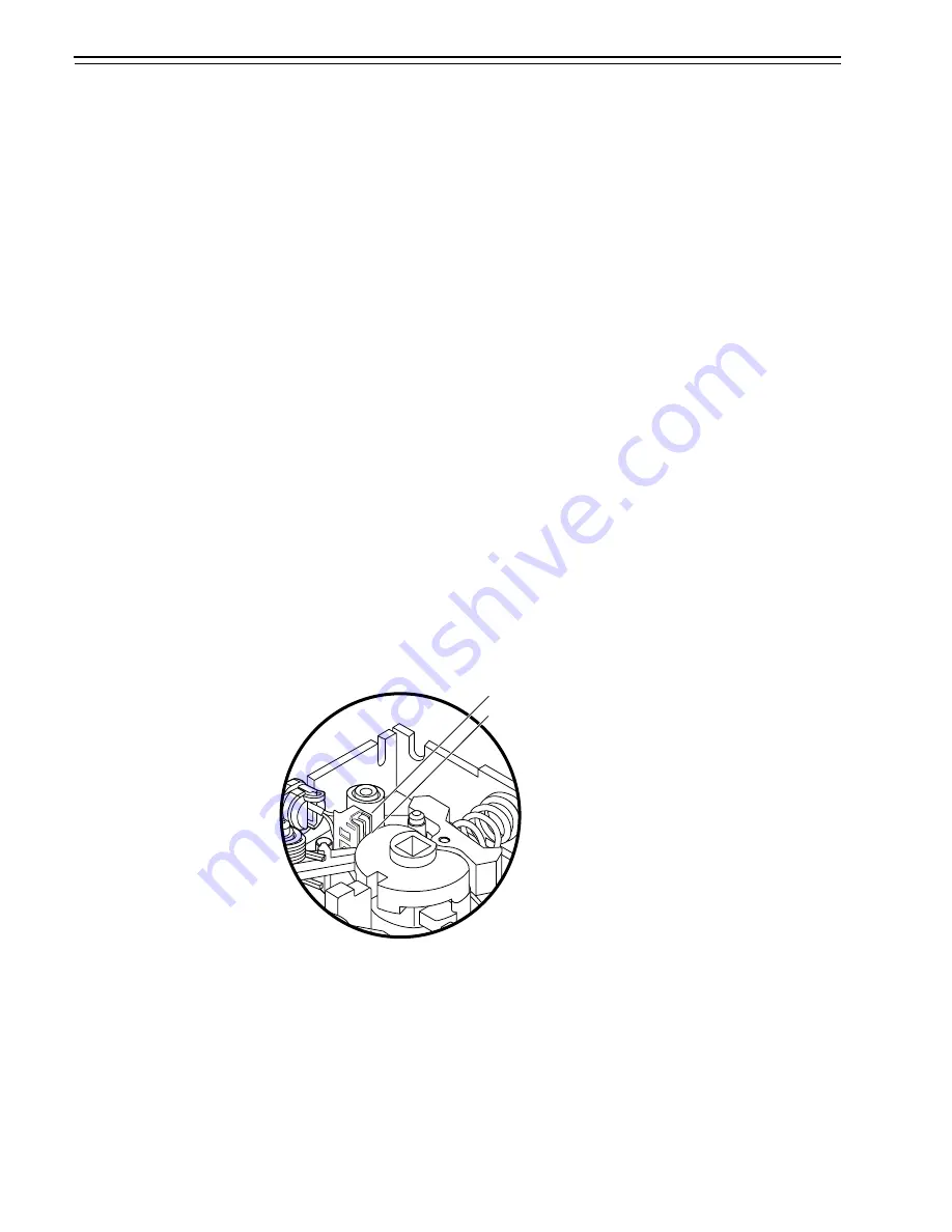
6. Tilt the RQE switch forward and remove it from the case.
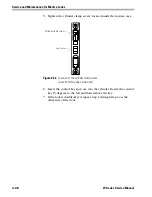
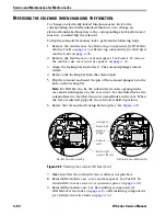
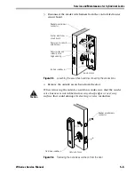
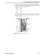
Figure 4.51
RQE switch and hub orientation (closeup)
Pivot point on the RQE switch
Flat side of the outside hub
Summary of Contents for 34HW
Page 1: ......
Page 6: ...Contents vi W Series Service Manual...
Page 38: ...IDH Max Locks Functions and Parts 2 24 W Series Service Manual...
Page 54: ...Electrified Locks Functions and Parts 3 16 W Series Service Manual...
Page 140: ...Service and Maintenance for Cylindrical Locks 5 30 W Series Service Manual...
Page 158: ...Additional Service and Maintenance for IDH Max Locks 6 18 W Series Service Manual...
Page 162: ...Glossary A 4 W Series Service Manual...
Page 164: ...Installation Instructions B 2 W Series Service Manual...