Service and Maintenance for Mortise Locks
4–46
W Series Service Manual
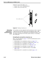
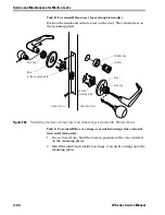
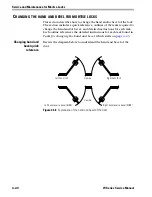
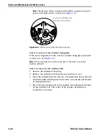
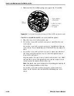
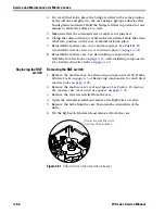
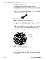
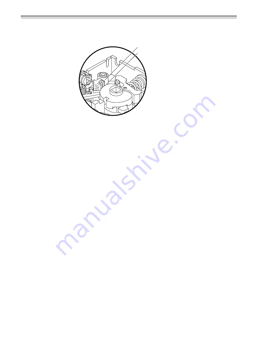
Note:
The flat side of the outside hub should be opposite the pivot
point on the RQE switch, as shown in
.
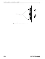
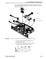
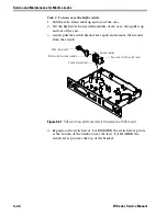
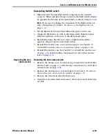
Task E. To turn over the cylinder clamp plate:
If the lock is single-keyed, turn over the cylinder clamp plate and insert
it in the case. See
Note:
The screw must be on the same side of the lock case as the
mortise cylinder.
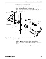
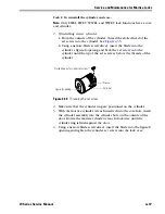
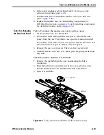
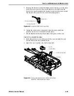
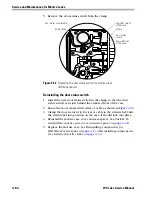
Task F. To turn over the auxiliary bolt:
1. Remove the auxiliary bolt spring.
2. Remove the auxiliary bolt from the case and turn it over.
3. Insert the auxiliary bolt into the case. The angled portion of the bolt
should be pushed through the front of the case and the feet should
be resting in the slot.
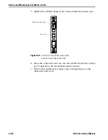
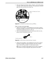
4. Place the long, straight end of the auxiliary bolt spring into the hole
on the auxiliary bolt. The center of the spring coil should rest
around the screw post.
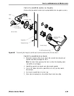
Figure 4.44
RQE switch and hub orientation (closeup)
Pivot point on the RQE switch
Flat side of the outside hub
Summary of Contents for 34HW
Page 1: ......
Page 6: ...Contents vi W Series Service Manual...
Page 38: ...IDH Max Locks Functions and Parts 2 24 W Series Service Manual...
Page 54: ...Electrified Locks Functions and Parts 3 16 W Series Service Manual...
Page 140: ...Service and Maintenance for Cylindrical Locks 5 30 W Series Service Manual...
Page 158: ...Additional Service and Maintenance for IDH Max Locks 6 18 W Series Service Manual...
Page 162: ...Glossary A 4 W Series Service Manual...
Page 164: ...Installation Instructions B 2 W Series Service Manual...