background image

17. Index 

FlowStar2 LB 514 


17.  Index 


A


Acetonitril buffer gradient 

123 

Admixture cells 

20 

Admixture method 

31 

Alphanumeric entries 

69 

Analog Input 

25 

Analog input settings 

77 

Analog output 

83 

Analog Output 

25 

Analog signals 

83 

Analytic cells 

30 

Analytic splitter 

43 

Inspection and troubleshooting 

48 

Analytic Splitter 

Installation 

46 

Autosampler 

24 

B


Background 

83 

Background values 

120 

Baudrate 

77 

Beta radiation 

32 

BGO 

28 

BGO-X cell 

32 

C


Capillaries 

Installation 

59 

Cell volume 

86 

Cerenkov effect 

32 

Cerenkov radiation 

20 

Cleaning the measuring cells 

36 

Cleaning the measuring chamber 

37 

Coincidence circuit 

21 

Coincidence time 

86 

Communication Monitor


100 

Computer connection 

23 

Configuration of the device 

76 

Configuration with Analytic Splitter 

44 

Configuration with solid cell 

17, 55 

Connecting steel capillaries 

34 

Connecting the supply system 

39 

Connections 

19, 22 

Scintillator pump 

38 

Consignes de Sécurité 

13 

Control voltage for detectors 

77 

D


Defining / Editing methods 

82 

Defining and starting a run 

91 

Delay time 

87 

Display configuration 

76 

Disturbances 

120 

E


Efficiency 

83 

Electrical connections 

56 

Electrical or mains disturbance 

120 

Eluate flow 

84 

Enable fraction collector 

78 

Enable LS-pump 

78 

Enable printer 

78 

Enable waste valve 

78 

Energy window 

80 

Error 

70 

External control 

24 

F


Fill time 

87 

Fingertight screw fitting 

36, 60 

Flash effect 

124 

Fraction collector 

23, 86 

Fraction collector settings 

87 

Fraction collector,  time window 

88 

Function keys 

68 

Function of measuring cells 

92 

Fuse 

26 

FWHM 

83 

G


Gamma radiation 

20, 28, 32 

Getting Started 

54 

H


Half-life 

80 

Heterogeneous method 

28 

High voltage 

22 

Homogeneous admixture method 

28 

Summary of Contents for FlowStar2 LB 514

Page 1: ...setzt wer den These units are not designed for use in hazardous areas The units supplied should not be repaired by anyone other than Berthold service engineers or technicians authorized by Berthold Im Störungsfall wenden sie sich bitte an unseren zentralen Kundendienst In case of operation trouble please address to our central service department BERTHOLD TECHNOLOGIES GmbH Co KG Calmbacher Straße 2...

Page 2: ......

Page 3: ... 3 5 Cleaning the Measuring Chamber 37 4 SCINTILLATOR PUMP 38 4 1 Connections 38 4 2 Connecting the Supply System 39 4 3 Mixers 42 5 ANALYTIC SPLITTER 43 5 1 Description 43 5 2 Installation 46 5 3 Inspection and Trouble Shooting 48 6 VALIDATION USING 3H UND 14C TEST SOURCES 49 6 1 Checking the FlowStar with test sources 50 7 STARTUP OF THE HPLC SYSTEM 54 7 1 Preparations 54 7 2 Electrical Connecti...

Page 4: ... Controller 95 12 2 Controller Backend 96 12 3 HPLC Data Monitor 106 12 4 CHROMELEON driver 107 12 4 1 Installation 107 12 4 2 Program File Wizard only CHROMELEON 6 x 113 12 4 3 Sample Program File 115 13 EXPLANATIONS 116 13 1 Peak Half Width Time Constant Smoothing 116 13 2 Efficiency Correction 119 14 DISTURBANCES 120 14 1 Electrical or Mains Disturbance 120 14 2 Background BG 120 14 3 Luminesce...

Page 5: ...FlowStar software are printed in bold type face Measurement The selection of an option on a menu is written as a sequence of commands separated by a ver tical line Device Configuration Display pages and parameters are also printed in bold type face Edit step Function keys are printed in bold type face inside angular brackets Start Stop Enumerations are highlighted by Action steps are identified by...

Page 6: ......

Page 7: ...s to make sure that the instru ment will be set up and installed properly to guarantee safe operation Using the instru ment in other manner than described in the manual can result in damage of the instru ment other system components and can also cause user injuries The instruments are tested by the manufacturer and supplied in a condition that allows safe and reliable operation This equipment must...

Page 8: ...al measuring systems To disconnect the instrument from power the appliance coupler has to be removed from the mains The mains inlet of the instrument is located at the rear panel see 7 2 Service and repair work may be carried out by qualified personnel only The operator may only perform the maintenance work described in this user guide There are no exchangeable electrical components in the instrum...

Page 9: ...ystem with external HPLC Controller PC and or other equipment Hazards resulting from application caused by supplied measur ing substances and evaluation of the measured values by external analyses must be considered in end system application The tests and service work recommended by the manufacturer has to be performed to make sure that the operator remains safe and that the instrument continues t...

Page 10: ... zu Verletzungen des Benutzer führen Die Geräte sind werkgeprüft und wurden in betriebssicherem Zustand ausgeliefert Die Geräte dürfen nur von autorisierten Personen in Betrieb genommen und nur von eingewiesenem Personal bedient werden Alle Benutzer die mit den Geräten arbei ten müssen zuerst diese Bedienungsanleitung lesen Bitte beachten sie die örtlichen Bestimmungen zum Umgang mit radioaktiven ...

Page 11: ...eb ist Service und Reparaturarbeiten dürfen nur von Fachleuten ausgeführt werden Es dürfen nur die im Handbuch beschriebenen Wartungsarbeiten vom Anwender aus geführt werden Bei Wartungsarbeiten dürfen nur die angegebenen Teile verwendet werden Um das Gerät vollkommen vom Netz zu trennen kann das Netzkabel gezogen wer den Der Netzeingang befindet sich auf der Rückseite siehe 7 2 Gerät ausschalten ...

Page 12: ...lten sie beabsichtigen höhere Flussraten einzusetzen kontaktieren sie bitte den Hersteller Die 12V Anschlüsse an der Geräterückwand entsprechen nicht den Anforderungen an sog limited energy circuits Das Gerät ist Teil eines HPLC Gesamtsystems mit Steuermodul PC und oder ande ren Komnponenten Gefahren die aus der Anwendung der Proben hervorgehen sowie die Auswertung der Messwerte auf externen Syste...

Page 13: ...est soumise s à des réglementations prescrites par la loi il appartient à l utilisateur de les respecter Le constructeur a fait tout le nécessaire pour assurer le fonctionnement sûr des appareils du point de vue électrique électronique et mécanique L utilis ateur est tenu de veiller à ce que les appareils soient installés correctement afin d éviter toute altération de leur utilisation sûre Les app...

Page 14: ...ne fiches à 3 broches dont une prise de terre C est une prescription de sécurité Il est nécessaire que cette fiche puisse être branchèe sur prise reliée à la terre Dans le cas contraire il vous faut alors en avertir un électricien afin d installer une telle prise Il ne faut pas négliger cette consigne de sécurité Les appareils correspondent aux prescriptions de la norme C I E 61010 1 ou EN 610 10 ...

Page 15: ...explosif Respecter toutes les prescriptions légales concernant la manipulation des déchets biologiques des réactifs et des prélèvements échantillons de patients L utilisateur assume la responsabilité exclusive de l utilisation des réactifs Pour le nettoyage de l instrument veuillez vous référer au paragraphe correspondant dans ce mode d emploi Le fonctionnement correcte ne peut être garantit qu à ...

Page 16: ...itor The Radioflow Detector is employed for the measurement of all liquid sources commonly used in radiochromatography HPLC measurements detect and radiation using various measuring cells which are installed downstream of separation column and mass detector UV monitor The microprocessor performs the following control and process functions setting of energy channels data reduction of radioactivity ...

Page 17: ...onitor and measured The eluate flow is split via the 2 3 way valve V and the radioactive peaks are collected in the vials of the fraction collector FC connections for commands and data transfer control lines _______ capillary supply lines for eluate sample and scintillator FlowStar comprises the following system components a microprocessor for data reduction of the radiation channels waste or frac...

Page 18: ...ntrol e g injector valve or autosampler etc Recorder Analog Output Connection of PC FlowStar can be connected to a PC via the USB interface In this case the computer controls the operation of the monitor Additional functions such as data reduction and storage of parameter sets are now available If the computer is in charge no data can be entered via the touch screen monitor In the following chapte...

Page 19: ...l FlowStar All connections are established on the rear panel of the device Mains con nection Mains and mains fuse Fuse are also located on the rear panel Figure 3 Rear panel of FlowStar with connection ports and terminal connections FlowStar LB 514 2 Status READY Cell Test 14C LS Pump OFF Time HH mm ss ELAPSED 00 00 00 125 4 20 10 0 0 2 4 6 8 CPM C 14 I O Status READY Cell Test 14C LS Pump OFF Tim...

Page 20: ... seals off light The measuring cell itself is usually a spiral shaped thin Teflon hose through which the eluate is flowing The radioactive la beled substances in the eluate flow are detected by means of scintillator either solid scintillator located stationary in the measuring cell or liquid scintillator which is added to the eluate The measuring cell is located be tween the photo cathodes of two ...

Page 21: ...ltiplier These electrons are accelerated by the high voltage applied and move toward the anode their impact on a dynode system gen erates further electrons The resulting current pulses are then amplified and selected in the discriminator The main task of signal evaluation is to detect counts caused by radioactive decays and to distinguish them from counts caused by Luminescence Photomultiplier noi...

Page 22: ...he Mon itor The high voltage is turned on only if the measuring cell has been fixed correctly This protects the photomultiplier against incidence of light An measuring chamber outlet connector 6 is also located underneath the measuring cell This should be connected to a waste container In case of a cell leak the leaking liquid is guided out of the measuring chamber through this tube Figure 4 Front...

Page 23: ... no 26204 Zero Modem cable included with the scope of supply of the pump The scintillator pump LB 5037 is controlled through the serial port of the FlowStar The socket 9 pin male sub D is located next to the USB con nector The connection cable is included with the scope of supply of the pump The 9 pin Sub D socket labeled Pump analog is the connection socket for the control of the older scintillat...

Page 24: ...hat the detector is ready to measure and waits for a start signal This signal can be used to trig ger an autosanmpler to inject a sample Lumi High Luminescence signal This signal is active in case a high luminescence state is detected if enabled in the sys tem settings A high luminescence usually indicates mixing problems in case of liquid scintillation method or a light leak due to improper tubin...

Page 25: ... supplied loose ends or HPLC system specific cables Pin assignment for the 1st counting channel Out1 output signal GND or Analog ground Shield shielding pin for the 2nd counting channel Out2 output signal GND or analog ground Shield shielding pin If only one counting channel is activated the output signals are always applied to the 1st counting channel Analog Input External detectors for example U...

Page 26: ...the power socket Fuse rating 250V T1 0 AH 5 x 20 mm Protection type Protection class I according to VDE 0100 Figure 5 Rear panel of FlowStar with connection ports and terminal connections BERTHOLD TECHNOLOGIES 75323 Bad Wildbad Made in Germany ID Nr VAC Hz VA Träge Netzsicherung Slow Blow Fuse 1A CE USB Pump analog Pump RS 232 Waste FC Waste Via l 12V D GND External Control Star t Stop Ready Error...

Page 27: ...essive substances in ad dition to the radioactivity which have to be removed completely as they can also reach the PMTs Otherwise they will continue to have a harmful effect on the device and may ultimately damage it For this reason the device should be cleaned by BERTHOLD TECHNOLOGIES service personnel In solid cells the eluate includes radioactive substances which have to be removed carefully ta...

Page 28: ...the measuring cells a Cells with solid scintillator YG MX b Homogeneous admixture method Z c Special methods for Gamma radiation J and BGO d Measurement of high energy beta radiation using the Cerenkov effect without scintillator Z Identification of the cells The cells are marked on their front plate by letters and numbers which have the following meaning and order Example YG 150 U 5 D The first l...

Page 29: ...G 75 S6M YG 150 S6M 55215 53262 53259 55210 Measuring cell with surface treated Yttrium glass scintillator and small volume and low dead volume in and outlets for Micro HPLC application Max flow rate 1 1 5 ml min Cells with Yttrium glass scintillator 100 Z 500 5 Z 1000 5 50154 50153 Analytical admixture cells with high est sensitivity The cells can simulta neously be used for 32P measure ment via ...

Page 30: ... this User s Manual Application For Alpha and Beta labels 3H 14C 35S 90Sr etc Volume 10 400 µl larger volumes on request Filling material Glass Yttrium glass The grain size is optimized with regard to efficiency and backpressure An alytical cells have a small preparative cells a large grain size Handling Easy handling good tolerance of all eluates rare memory effects removal of possible contaminat...

Page 31: ...litter to minimize liquid scintillator consumption and or to re use the eluate Liquid scintillator with certain properties it should absorb the existing eluate without any problems the resulting cocktail should remain trans parent without jellification crystallization or flocculation Moreover no mixture gaps or luminescence must occur Volume 20 µl 1 ml Handling No contamination or memory effects a...

Page 32: ...y to detect by means of the Cerenkov effect Common admixture cells with the desired volume are employed for the measurement of Ceren kov effects Light pulses are generated in the cells which can be detected with high efficiency Essential advantage of this method very low back ground due to the fact that no scintillator is in the counting chamber There fore excellent detection limit E2 BG Identific...

Page 33: ...t the high voltage is turned on only if the counting chamber is closed It informs the system about the parameters of the measuring cell This ensures that only methods can be used during a run which are suitable for this measuring cell Figure 6 Front view of FlowStar Monitor Light seal and incidence of light An O ring seal 59 x 2 mm protects the measuring chamber against light Make sure the seal is...

Page 34: ...pillaries do not ensure any light sealed operation When using Teflon capillaries a 10 15 cm long steel capillary piece should be used before each cell in and outlet shape it in the form of a spiral or a wave to suppress any light guide effect The outlet capillary must always have a larger inner diameter than the inlet capillary see Figure 7 Outlet capillary in solid cell min ID 0 5 mm Outlet capil...

Page 35: ...8 CPM C 14 I O Status READY Cell Test 14C LS Pump OFF Time HH mm ss ELAPSED 00 00 00 125 4 20 10 0 0 2 4 6 8 CPM C 14 IN OUT T Mixer ID 0 5 mm min ID 1 mm FlowStar LB 514 2 Status READY Cell Test 14C LS Pump OFF Time HH mm ss ELAPSED 00 00 00 125 4 20 10 0 0 2 4 6 8 CPM C 14 I O Status READY Cell Test 14C LS Pump OFF Time HH mm ss ELAPSED 00 00 00 125 4 20 10 0 0 2 4 6 8 CPM C 14 IN OUT max ID 0 5...

Page 36: ...using a solvent In case of heavy contamination the cell has to be decontaminated if in doubt replace it The measuring cells are cleaned by means of a PE disposable syringe 2 or 5 ml as follows Unscrew the inlet capillary Prepare a coupling so that disposable syringe and measuring cells inlet can be fitted together accurately Use a 200 µl pipetting tip yellow and cut it on both ends by 8 mm see pag...

Page 37: ...ion glasses and gloves Liquids from admixture cells often contain aggressive substances which have to be removed completely otherwise they will continue to have a harmful effect on the device and may ultimately damage it For this reason the device should be cleaned by BERTHOLD TECHNOLOGIES service person nel as this requires disassembling of the detectors In Solid cells the eluate includes radioac...

Page 38: ...nnection sockets are located on the rear panel of the pump Power supply 24V The 9 pin Sub D socket with cable no 26204 is used for external control via FlowStar The pump head is located on the front of the pump housing The inlet valve is installed on the bottom right of the pump head and the outlet valve for the liquid scintillator on the bottom left How to connect the supply system will be descri...

Page 39: ...this knee pipe piece type Iso Versinic OD 4 mm ID 2 mm also included with the shipment The other end is already connected to the filter The filter should always be clean In case of possible gel like deposits or impurities clean it using methanol or ethanol For cleaning the filter may be dismantled and the filter disc removed and if necessary replaced The pump inlet fitting of the tubing is mounted...

Page 40: ...ump head If the supply line is not completely filled e g if air bubbles exist when taking the pump into operation and occasionally after cleaning the pump a few preparations have to be carried out before starting to aspiration new scin tillator Two alternatives are possible a New aspiration by disposable syringe For fast aspiration of the scintillator liquid we recommend using a PE disposable syri...

Page 41: ...lied 60 cm long stainless steel capillary ID 0 5 mm with pre installed connection onto the outlet valve The pump is ready for operation b New aspiration by scintillator pump This procedure takes up more time and requires wet valves The arrangement is the same as described under a The liquid container is set on a higher level than the pump the supply line is connected the outlet not yet Switch on a...

Page 42: ...oming from the HPLC UV detector connects to the outher inlet The mixer oulet connects to the inlet of the FlowStar measuring cell The T mixer has a special capillary at the outlet the static mixer uses standard tubing OD 1 16 ID 0 5mm The static mixer consists of 3 parts Lower housing inlets are located here Upper housing outlet Cartridge 50 or 150µl When using the static mixer assemble the unit b...

Page 43: ... mixer T and passed on to the admixture cell of the HPLC Monitor The other share of the eluate is passed on to the fraction collector FC Standard versions of the AS xx have a splitting ratio of 15 25 33 and 50 These percentages define the share of the eluate which is passed on to the radioactivity cell Due to the very thin capillaries the system generates a backpressure of approx 5 bar at the inpu...

Page 44: ...nd increased only by a Teflon capillary When using a stainless steel capillary it must have a larger internal diameter Caution Total flow rate 2 ml min With a total flow rate from cocktail liquid scintillator split off elate of 2 ml min use a 60 mm long stainless steel capillary with an internal diameter of 0 5 mm between T piece and measuring cell When using longer or wider capillaries this may l...

Page 45: ...ive Figure 12 Configuration with subsequently connected UV detector If the backpressure created by the AS xx should cause a problem for the UV de tector you may connect the detector between Analytic Splitter and fraction col lector FC The capillaries C and FC have an internal diameter of 0 1 mm The capillaries after the T mixer to the admixture cell should have an internal diameter of 1 mm at a to...

Page 46: ...ate length into the silicon hose to pass the eluate on to the fraction collector C measuring cell AS xx T 0 1 mm ID T measuring cell 1 mm ID Use the capillary spiral attached to the AS xx as a connection to the T mixer T Here the split off eluate share is mixed with liquid scintillator transported to the radioactivity measuring cell where it is measured Due to the viscosity of the cocktail the in ...

Page 47: ...pumped into the eluate input of the Analytic Splitter by a pump and the splitting ratio checked using 2 measuring cylinders Caution The flow rate must be absolutely free of pulsation We recommend con necting the Analytic Splitter directly after the column ...

Page 48: ...ulsation reducer column check if the pulsation on the high pressure side has already been reduced Blocking or clogging in a capillary FC or C With eluates having a high buffer concentration it may happen that the thin capillaries ID 0 1 mm may be blocked by crystallization Remedy Flush the blocked capillary FC or C from the rear end with water and collect the water at outlet E Figure 14 Blocking t...

Page 49: ...tested in accordance with 150 DIN 9978 draft DIN 25426 see certifi cate Storage The test source should be stored well protected in a dark room Procedure An initial validation is necessary when the test source is used for the first time This initial validation measures the variation between the nominal value of the test source and the measured value of the detector and spec ifies an initial nominal...

Page 50: ...istory If the validation failed check the instrument and repeat the measurement Procedure and parameter entry Select Validation from the main menu This entry is only visible if you are logged in as supervisor The following menu appears Measurement Validation measurements are handled through this menu History Earlier successful validation measurements can be revied in the Validation history Paramet...

Page 51: ...D or FAILED is dis played depending if the results are within or outside the specified tolerance level In case of FAILED the measurement can be repaeted by pressing Start If the validation is Passed the results can be saved pressing the Save button A failed validation cannot be saved Menu Menu Pg Start 5 1 2010 TIME HH mm ss ELAPSED 00 00 00 Current value cpm Stat error 0 1 62546 Deviation nominal...

Page 52: ...ation Prerun Time Defines the waiting time before starting the validation measure ment This prerun time is used to calm down the test cell which V A LIDA TIO NHIS TO R Y 1 1 Test H 3 Test C 14 Test BG Test BGO Last next Validation Last Validation on 05 Jan 2010 Next Validation on 05 Apr 2010 Esc V A LIDA TIO NHIS TO R Y 1 1 Ident Number 49926 Serial Number 52003 Cell Type C 14 Scintillator Type Te...

Page 53: ...en the box is checked the instrument gives an error message when the validation is due The instrument cannot be used for measurements If the box is unchecked only a status message appears Validation is due and the instrument can be used Last Validation Shows the date oft he last successful validation Next Validation Shows the date when the next validation should be performed The date can be modifi...

Page 54: ...er that the capillary connections can be kept to a minimum length This is especially true for the column the UV detectors and the HPLC Monitor FlowStar Figure 15 shows an example of a possible setup The capillary connections are identified by straight ______ lines whereas the electrical connections are drawn as dotted lines To ensure a sufficient air flow through the fan a minimum distance of 10cm...

Page 55: ... in the HPLC monitor and measured The eluate flow is split via the 2 3 way valve V and the radioactive peaks are collected in the vials of the fraction collector FC connections for commands and data transfer control lines capillary supply lines for eluate sample and scintillator I 0 purge s tart s top I 0 purge s tart s top P1 P2 UV Detector Mixer Inj Col I 0 z ero wav elenght I 0 FlowStar LB 514 ...

Page 56: ...wise trouble may occur in the microprocessor units Use a multipole connector which is connected to the wall outlet Mains connections 1 FlowStar Main cable no LB 75800 25 Mains 2 FlowStar Ratemeter cable with open ends Integrator 3 FlowStar Ext Control cable with open ends Ext control 4 FlowStar Pump ser cable no ID 26204 Scint pump 5 FlowStar USB USB cable A B Computer 6 FlowStar Waste FC cable wi...

Page 57: ...l Ground Ext Control Start Start Signal Input Stop Stop Signal Input Ready Ready Signal Output Error Error Signal Output Wait Waiting for Start Output Lumi High Luminescence Output Aux Out Aux Signal Output Aux In Aux Signal Intput 12V Supply Voltage max 100mA DGND Digital Ground BERTHOLDTECHNOLOGIES 75323 Bad Wildbad Made in Germany ID Nr VAC Hz VA Träge Netzsicherung Slow Blow Fuse 1A CE USB Pum...

Page 58: ...d cap screws Fix the screws only slightly first and then tighten them alternatively Always fix the bottom screw first since the ID chip on the upper edge of the cell automatically activates the high voltage for the for the light sensitive detec tor if the HPLC Monitor is turned on Figure 17 Front view of Radioactivity Monitor FlowStar 1 built in measuring cell 2 fastening screw 3 inlet capillary I...

Page 59: ...apillary must be for Solid cells 0 5 mm and for admixture cells 1 mm 14 Cut the in and outlet capillaries to the proper length by using either a capillary cutter or a feather edge file to slightly scratch the capillary and then break it never pinch it off Check if the bore hole of the capillaries is open and the connection sleeves of the measuring cells are clean 15 Install the outlet and inlet ca...

Page 60: ...a piece of it protrudes at the other end Set screw onto the connecting piece and tighten it slightly Push capillary all the way into the screw and the connecting piece Fingertighten screw make sure it is tight and if you detect any leakage tighten screw a bit more 16 Depending on your system setup connect the outlet capillary to the waste container or when using a waste valve or fraction collector...

Page 61: ...n push capillary through screw and jam cone with the screw thread and the tapering end of the jam cone facing the T mixer Push capillary through so that it projects by about 2 3 mm on the other end insert it into the T mixer and fasten the screw Tighten the screw fitting only so much that the connection is leak proof In the same manner fix the capillary coming from the column the UV de tector or t...

Page 62: ...el is the so called cold outlet This outlet is active if the status is on non radioactive waste It must be connected to the waste container collecting the non radioactive waste using the tube with the black fitting The outlet with the red color label is the hot outlet This one is active if the counting level is above the defined threshold It must be connected to the waste container collecting the ...

Page 63: ...idually activate or disable the waste valve A delay time switch on and switch off level can be defined within each method The delay time from detecting the peak until this fraction reached the valve outside must be calculated tube diameter and flow rate required or measured e g with an air bubble as position indicator C O NFIG UR A TIO N 2 3 LS Pump installed Fraction Collector installed Waste Val...

Page 64: ...ired This software comes with the in strument and allows complete remote control of the instrument as well as test functions The software is designed for Windows 7 8 and 10 32 and 64 Bit systems To install the software launch the file setup exe located on the installation media CD of USB stick A welcome screen will show up Click on next to get to the next screen ...

Page 65: ... installation is finished a summary page will appear Since the controller uses the TCP IP protocol for communication a firewall warning message will show up when the controller starts up the first time To guarantee a proper function of the con troller communication must be allowed If there will be no permis sion the controller cannot work properly In this case the windows firewall must be set to a...

Page 66: ......

Page 67: ...ement menu is displayed together with the curve dia grams of both counting channels The device goes directly to the Rateme ter mode and displays the measured values as a curve In addition to the 3 info buttons in the top section of the display which are used to view the parameters you can only select the function key for pass word entry The other options are available for selection only after you ...

Page 68: ... ure 19 or from a parameter page back to the Main menu Possible changes are taken over and stored Menu Takes you from the Measurement menu to the Main menu This button is not displayed during a run S ta rt S to p Starts or stops a measurement Pg Scrolls through the measurement menu to the next page X Push this button to move the measurement image back by one display width Thus you can scroll back ...

Page 69: ... the Measurement menu to the Main menu To select a menu on the Main menu push the button with the respec tive menu name This takes you to a parameter page or to a further branch On a parameter page a submenu is identified by 3 dots next to the submenu name e g Display configuration in the following illustra tion To select the submenu highlight it and then push the key Figure 20 Parameter page with...

Page 70: ... flashing inverse Warning and Error there is an additional acoustic signal Ready display The device is ready for measurement no error warning info messages are displayed Error display An error has been detected the measurement was stopped completely Error events Leakage Counting chamber open Detector A B HV off Cell chip error Detector error Warning display A warning event has occurred no errors h...

Page 71: ...w you do not go to the cell parameters instead a page comes up showing more information on the error that has occurred LS pump button This button is displayed only if an LS pump is connected and the respective parameters have been entered Regular operation During regular operation the current status of the LS pump is displayed next to the button on or off Push the button to view the pump parameter...

Page 72: ...follows On the Measurement menu push the button A new window ap pears showing the types of users that are available for selection To select a user type highlight the desired type and select it with the button If you have selected User the program returns to the Measurement menu and shows further function keys for operation If you have selected Device administrator a complete alphanumeric keyboard ...

Page 73: ...D Cell Volume µl 150 Coincidence Time ns 12 Method Method 1 Method Parameters Current Cell Current Method ME THO DS 1 2 Method 0 Method 1 Method 2 Method 3 Method 4 Method 5 Method 6 Method 7 Method 8 Method 9 Method 10 Method 11 Individual methods M E THO DP A R A M E TE R S 1 2 Name Method 1 Unit cps Peak FWHM s 4 Active x Nuclide C 14 Background cps 0 0 Efficiency 0 0 Spillover into Ch 2 0 0 Va...

Page 74: ...y Configuration Backlight timeout min 5 Adjust Display Contrast 78 Control Voltage Det A V 1 300 Baudrate 9600 Plug In Card installed x Analog Input Settings Control Voltage Det B V 1 300 LCD Display Electrical Parameters Communication Port External Analog Inputs C O NFIG UR A TIO N 2 3 LS Pump installed Fraction Collector installed Waste Valve installed Printer installed Time 14 02 23 Date 17 Aug...

Page 75: ... the parameter entries in the following order Configuration of the device with connected devices Nuclide parameters with threshold values and permitted measuring cells Measuring cell parameters automatically defined by the cell that has been inserted Definition Selection of methods Definition of measurement parameters parameters for one run Once the basic configuration of the device has been set u...

Page 76: ...nels are to be displayed and how the measurement diagrams should be arranged on the Measurement menu Select Display Configuration and push the button to go to the param eter input Define on which page the radioactivity signals and where channel 1 and chan nel 2 are to be displayed Highlight 1st page Top Graphic and push In the following selection list Top Graphic select the channel that is to be d...

Page 77: ... only accessable through service personal Data comm interface Baudrate The baudrate is 9600 External analog inputs Plug in card in stalled Tick the checkbox x if you have installed a plug in card for analog inputs To enable disable this item highlight it and then push the button Analog input settings If a plug in card is installed you have to define the following parameters Analog input settings A...

Page 78: ...an be used to calibrate the pump to a specific scintillator Due to different viscosity of liquid scintillators the real flow rate can differ from the preset flow Using the calibration facto the flowrate can be cor rected to get correct flow rates Default is 1 000 Count if pump is off If this box is ticked the FlowStar will display no counts if the scintillator pump is not running Data Output Delay...

Page 79: ... enter one password for the user level and one for the de vice administrator level Test cell installed This setting is for external gamma test sources If the box is checked the BGO cell is enabled to perform a system validation since external gamma test sources do not have an ID chip Language Here you define the language for the user interface German or English ...

Page 80: ...pages you can define your own nuclides These have the default name Def 11 Def 12 etc or USR 0 USR 1 etc Editing a user defined nuclide Highlight the desired nuclide Defxx or USR x and push the button The page with the respective nuclide parameters is displayed Name Enter a name for the nuclide max 6 characters Enabled Only if the checkbox of a nuclide is ticked x it can be selected for a method Ha...

Page 81: ...e used to measure this nuclide Only those nuclides are offered for selection in the method definition which are permitted for the installed pre selected measuring cell C E LLS A LLO W E D 1 1 YG x GT x CaF x Z I BGO Meltilex Test H 3 Test C 14 Test BG Figure 26 Permitted cells are identified by an x ...

Page 82: ... Active x Nuclide C 14 Background cps 0 0 Efficiency 0 0 Spillover into Ch 2 0 0 Value at 1 V Unit V 1000 Time constant FWHM 2 Channel 1 Analog Output Figure 27 Left List of methods Right Method parameters page 1 The individual parameters Name Enter a name for the method Unit Select the desired unit Push the button to display the selection list with the possible units cps cpm Bq dps dpm and the di...

Page 83: ... is not relevant see remarks below In this case you also have to enter 0 0 Analog output Settings for the analog output Smoothed analog signals that are propor tional to the measured count rate will be output here You have to define the measuring range within which the count rate is to be expected Value at 1 V Unit V Enter the expected measuring range that corresponds to 1 V Entering 1000 means th...

Page 84: ...put setting e g 1 000 the other channel should be set to a high analog output setting e g 100 000 or 1 000 000 to display the higher intensity peaks more precisely and avoid an overflow Method parameters page 2 M E THO DP A R A M E TE R S 2 2 Aktive x Nuclide H 3 Background cps 0 0 Efficiency 0 0 Spillover into Ch 1 0 0 Value at 1 V Unit V 1000 Channel 2 Analog Output Figure 28 Method parameters p...

Page 85: ...red parameters Push Esc to exit this these page s The measurement parameters will be stored The program returns to the main menu On the main menu push Esc The program goes to the Measurement menu If you push S ta rt on the Measurement menu the run will be started with these parameters In the top row of the Measurement menu the method used and the name of the run are displayed alternatingly as defi...

Page 86: ...to replace the measuring cell Cell volume µl Cell volume in µl Coincidence time ns Is defined by the measuring cell used decay time of the scintillators Solid cells 100 nsec Liquid cells 30 nsec Current method Select the desired method Method XXX Selection and display of the desired method for this run Push the button to view the selection list with the methods that are compatible with the measuri...

Page 87: ... of this item you go to the page Waste valve parameters Figure 32 Fraction collector settings FR A C TIO NC O LLE C TO RS E TTING S 1 1 Controlled by Level Vial Volumen ml 10 0 Fill Time s 2 0 Delay Time s 1 0 Active from 00 00 00 Active To 00 00 00 On Threshold 100 0 Off Threshold 0 0 Time Window Level Thresholds Figure 31 Fraction collector settings Controlled by Control of the fraction collecto...

Page 88: ...ime in seconds Waste valve parameters W A S TEV A LV ES E TTING S 1 1 Delay Time s 1 0 On Threshold 100 0 Off Threshold 0 0 Level Threshold Figure 32 Waste valve parameter Delay time s Time delay from the cell output to the waste valve This time delay de pents on the specific flow rate and the length of the tubing used and must be tested individually Threshold value Enter the low and high threshol...

Page 89: ...xternal hardware scin tillator pump waste valve etc is controlled though the FlowStar It re quires either a manual start touch screen or an external start signal 10 1 Measurement Menu The currently measured values of both counting channels are displayed graphically and numerically on the Measurement menu Push Pg to switch between display of the radioactivity and the analog signals Info row and inf...

Page 90: ...nt menu and there select the method again for the respective run Only then the changed method will be loaded Now go to the Measurement menu and start the measurement Only then the new parameters will be used in this case the new energy window of the nuclide This also means that in all methods which use the nuclide XY the nu clide has to be loaded again so that the new nuclide parameters will be us...

Page 91: ...s described in the previous section Exit the measurement parameters page with Esc The program returns to the Main menu Push Esc to go to the Measurement menu Push the S ta rt button Starting a run externally If Start mode external is defined in the measurement parameters and the necessary connections have been established the run is started stopped by an external start stop signal instead of pushi...

Page 92: ...ough stimulation by a scintillator The light pulses emitted in the measuring cells are registered by the detectors and converted into electrical pulses and analyzed and then downloaded to a data system for evaluation Radioactivity flow through detectors register radioactivity by means of scin tillators or via the Cerenkov effect The radioactive atoms in the labeled substances disintegrate and exci...

Page 93: ... time 2 whereas luminescence events represent single photon emissions Only coincident events will be processed as useful signals A Presentation on the time axis B Presentation in the measurement chamber with PM 1 and PM 2 t t t PM 1 PM 2 coincidence T1 T1 T2 T2 radioactivity events luminescence events A PM 1 PM 1 PM 2 PM 2 Time 1 Time 2 T1 Time 1 T2 Time 2 PM1 Photomultiplier 1 Pm2 Photomultiplier...

Page 94: ... and energy The type of radiation tells us whether we are dealing with alpha beta gamma emitters etc The quantity of radioactivity is indicated in the following units Becquerel Bq dps decays per second dpm dpm decays per minute 1 Bq 60 dpm Curie Ci 3 7 1010 Bq or dps These quantities describe how many decays per unit of time second or minute take place in the sample For nuclides with shorter half ...

Page 95: ...By right clicking on the task icon a context menu pops up Login In order to get access to the user interface a login is required Choose Setup and a login page will show up For standard users the login is User without password The de fault administrator login is Service and password is 0 zero After the login the Controller setup page is shown Logoff Log off from the backend menu This might be requi...

Page 96: ...sh the remote control status and locks the instrument again Exit Shuts down the FlowStar controller 12 2 Controller Backend Instrument In the tab Instrument Configuration the current hardware con nection as well as the installed features can be seen Tab Instrument information shows the instrument information such as the order confirmation number of the instrument model serial number production dat...

Page 97: ...tegories Test H 3 Test C 14 Test BG Test BGO the test results of the validation measurements as well as the first validation can be reviewed as a table or graph For further information regarding the validation refer to chapter 6 The graphs and reports can be created by clicking on the Create Report link below the data window The validation report will look like this ...

Page 98: ...12 FlowStar Controller Software FlowStar2 LB 514 98 To print this report click on the printer icon in the icon bar ...

Page 99: ... window About The version number of the FlowStar Controller and other instru ment information can be seen in the About window Advanced Advanced tools for software updates and monitoring are offered in this section By clicking the controller connects with the Berthold Technologies webpage and checks if a newer version of the controller is available and downloads it after confirming The tool flash s...

Page 100: ... file is useful for the Berthold Technologies Support to iden tify communication problems and should be sent by email if this is requested by the suppport Communication Monitor If there are general problems with the instrument communica tion characters get lost etc the message monitor can be used to record the instrument communication The Monitor opens when clicking on This list of commands can be...

Page 101: ...setup of the analog acquisition channels the scintillation pump type etc are defined The label of the signal the voltage range and poliarity can be defined for each individual channel see chapter 9 1 Depending on the pump is used with the FlowStar the correct type must be selected from the list see chapter 9 1 ...

Page 102: ... section offers testing functions for the scintillation pump the Fraction collector as well as the waste valve A flow rate for the pump can be set and the pump can be started and stopped According to the configuration the pump is controlled through the serial port LB 5035 3 LB 5035 3M or LB 5037 or via the analog output and status signals at the Scint Pump Con nector By clicking or the relay outpu...

Page 103: ...reset the output This feature is very useful to check if the analog output port which might be connected to an external HPLC system through an A D converter works properly output value and signal polarity Isotopes The isotope editor is a tool to browse through the table of nuclides which are stored in the FlowStar The table of nuclides for the Standard nuclides is read only and cannot be modified ...

Page 104: ...e brightness of the LC display and the timeout for the backlight will be set Display To configure the FlowStar Touch Screen use the tab Display The preferences for displaying the different signals can be de fined here To get 2 pages with full screen signal select any signal in the upper graph box and none in the lower graph box For further information on these parameters please refer to chapter 9 ...

Page 105: ...he validation is due Luminescence warning threshold can be defined in pro cent of the signal Date Time By clicking on the button the current PC time will be transferred to the FlowStar User Management The FlowStar has two user levels User and Service In this di alog box the passwords for these two users can be modified The User has no deafult password for Service is the default pass word 0 zero Th...

Page 106: ...oller When launching the Monitor the following user interface pops up On the left hand side is all relevant information of the instrument available while the current data are shown on the right side The signal channels are shown in different tabs By clicking on one of these tabs the corresponding signal is displayed On the left side is all relevant information over the instrument such as instrumen...

Page 107: ...9 but works on 7 x versions as well To be able to use the FlowStar driver a so called Class 3 license of Chromeleon is required 12 4 1 Installation Before installing and configuring the CHROMELEON driver using the Server Configuration Tool Instrument Configuration Man ager in CM 7 x the FlowStar Controller must be installed see Chapter 7 7 Be sure to check the relevant features for your cor respon...

Page 108: ...ents Select the item FlowStar from the list of devices and click to continue After a while the driver configuration dialog pops up to enter spe cific parameters When the FlowStar is connected to the local PC where Chro meleon is running retain all default values for the address com mand port and data port If Use Foreign Host is activated the hostname of the PC must be entered on which the FlowStar...

Page 109: ...signal names can be de fined Keep in mind that a change of these names later on may require to change all your program files because these names address the signals directly Click on continue In this dialog the default measurement configuration for channel 1 can be defined For further information about the measuring parameters refer to chapter 9 4 After clicking on the pa rameters for channel 2 ca...

Page 110: ...nd eluate can be defined in this box Please note that this function is only available if a liquid scintilla tor pump is activated in the FlowStar and as well a Z cell is in stalled The flow rate from the eluate is required when cpm dpm dps or Bq values should be calculated By clicking on installed cell further information on the currently installed cell will be shown When clicking on the fraction ...

Page 111: ...nding on the de vices used The possible different configurations measuring cells flow rates etc are saved locally at the PC where the configura tion was done This means a configuration might not be available using specific client Servers setup structures server and server configuration done on different PCs In this case the configuration files XFS can be copied man ually from the source PC path C ...

Page 112: ...splay the count rates from the detectors and show the status of the signals In addition several testing functions are available e g to set the analog output voltage to a specific value in order to test the connected A D converter But tons to start stop the data acquisition are located on the right side of the panel If no data is shown the Acquistion state must be set to on and the measurement mode...

Page 113: ...s must be checked The channels labelled with raw represents raw data channels without any calculated cor rections In this dialog the required configuration Isotope efficiency units etc can be selected In case that the required configuration is not available can be a new configuration created by clicking on To modify an existing configuration click on For print out the selected configuration for do...

Page 114: ...e edited manually see 12 4 3 The possible different configurations measuring cells flow rates etc are saved locally at the PC where the configura tion was done This means a configuration might not be available using specific client Servers setup structures server and server configuration done on different PCs In this case the configuration files XFS can be copied man ually from the source PC path ...

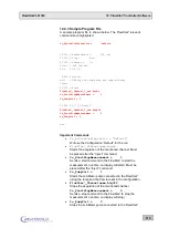
Page 115: ... Commands fs_ActiveConfiguration Default Will use the Configuration Default for the run FlowStar _Channelname AcqOn Starts the acquisition of the mentioned channel Must be placed after the Inject command fs_StartStopMeasurement 1 Sends a start command to the FlowStar to start the measurement run time on display will start Must be placed after the Inject command fs_PumpCtrl 1 Starts the scintillato...

Page 116: ...he optimum fit of the smooth to the peaks The peak half width is used to fit the curve smooth to the ex pected peak width When using a too high peak half width the smoothing procedure will result in a flattening of the peaks smaller or overlapping peaks will not be detected If this param eter is too small random variations will falsely be identified as peaks In praxis the expected peak width is kn...

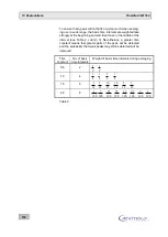
Page 117: ...go will be re jected The counts change in one second intervals even if the basis time intervals are longer than 1 second Averaging over several second intervals results in a significant smooth of the var iations The further procedure for calculating a smoothed average value always proceeds from the counts in these groups By entering one time constant one defines how many basis time intervals with ...

Page 118: ... the interval see Table 2 column 3 Nevertheless a greater time constant means that greater parts of the peak will be detected and the probability that weak peaks may still be detected will be improved Time constant No of basis time intervals Weight of basis time intervals during averaging 0 5 2 1 2 1 2 1 0 4 1 8 3 8 3 8 1 8 1 5 6 1 32 5 32 10 32 10 32 5 32 1 32 2 0 8 1 128 7 128 21 128 35 128 35 1...

Page 119: ... 5 7 The net cpm values are calculated as follows cpmnet cpmgr Background cpm dual Ch cpmnet cpmgr Background cpm H cpmnet Spill Ch1 Ch2 100 These formulae show that for dual channel measurements the net cpm value of the higher energy channel must be calculated first since this value is required for the spillover correction For single channel measurements the formula is identical to the first form...

Page 120: ... measuring system HPLC pumps gradient controller UV detector integrator radioactivity flow through monitor computer etc to one mains phase Check mass connection eliminate any possible crossover resistance or loose contact We recommend using mains suppression filters Schaffner filter sup plied by our Service Department 14 2 Background BG Table 2 lists typical background values These values may diff...

Page 121: ...In this case only the instrument BG has to be meas ured For service personnel we recommend measuring the individual rate of PM A left and PM B right in the SERVICE menu The individ ual rate is normally between 50 and 450 cps If the measurement cham ber has been open for a long time these values may be higher Cau tion Both PM s always have different single rates Up to 1000 cps will be compensated w...

Page 122: ...Cover capillaries with black shrinking tube or insulation tape several layers min 30 cm or use stainless steel capillaries Please note that PEEK capillaries are not light tight A black 15 cm long black protective hose may help We recommend using Norprene a black silicon like hose with an external diameter of 4 mm and an internal diameter of 2 mm to cover the PEEK capillary The Norprene hose is use...

Page 123: ...ence refers to light events occurring so often that they cannot be compensated any more by the coincidence circuit and consequently may disturb the measurement process in the measuring cell These single pho ton events occur mainly in the low energy channel but cause no interfer ence in the high energy channel with increased lower level LL 050 to 100 Phosphorescence Some organic solvents are excite...

Page 124: ...apillary mixer Increase in some cases reduce the scintillator share in the cocktail Flash effect Interference in solid cells With some purely organic non conductive sol vents n Hexan chloroform static charge effects are noticeable at a higher flow rate The friction of the molecules produces a static voltage which is not carried off due to the high resistance of the eluate Consequently the voltage ...

Page 125: ...de the device Turn device off immedi ately and separate it from mains For information on how to proceed please refer to Chapter 3 5 Cleaning the Counting Chamber Counting chamber open The counting chamber is not completely closed Check if the measuring cell has been inserted correctly and fixed with screws Detector A B HV off Detector does not get any or too little high voltage Check the HV parame...

Page 126: ...ed automatically if Error is displayed Push the Cell button to view further information on the error Display Error when the LS Pump button is pushed The measurement is stopped automatically if Error is displayed Push the Pump button to view further information on the error 15 1 Instrument cleaning The instrument can be cleaned using a soft cloth to remove dust etc In case of significant staining a...

Page 127: ...ollector Scintillator pump control with status signal and voltage controlled flow rate 2 analogue signal outputs 0 1V 2 5 times oversampling Waste valve and fraction collector control output 12V Supply voltage max rating 100mA per port Software Built in software operated with touch screen or external control and evalu ation via RadioStar or Chromeleon driver Power Supply 90 264 VAC 50 60Hz Power c...

Page 128: ...tion with Analytic Splitter 44 Configuration with solid cell 17 55 Connecting steel capillaries 34 Connecting the supply system 39 Connections 19 22 Scintillator pump 38 Consignes de Sécurité 13 Control voltage for detectors 77 D Defining Editing methods 82 Defining and starting a run 91 Delay time 87 Display configuration 76 Disturbances 120 E Efficiency 83 Electrical connections 56 Electrical or...

Page 129: ...2 84 Mixers 42 static 42 t piece 42 Mode of operation 16 N Nuclide parameters 80 O Operation of the software 68 Outlet capillary 30 34 Overview Menus and functions 73 P Parameter entries 75 Parameter page configuration 76 Password 72 79 Peak half height width 83 Peak half width 82 Permitted cells 80 Photomultiplier 21 Power on of the device 67 Preparative cells 30 Printer setup 78 R Radioactivity ...

Page 130: ...17 Index FlowStar2 LB 514 Test sources 49 Time constant 83 Touchscreen monitor 68 Typographical conventions 5 U USB 23 V Validation 49 Vial volume 87 W Warning 70 Waste 23 Waste valve parameters 88 ...

Reviews: