Bertazzoni B3W0..U4X2D Installation And User Instructions Manual Download Page 7


7

WARNING: Disconnect power before servicing unit. 

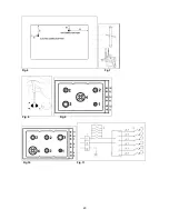
For the location of the wall receptable for the connection of the three-pin earthed plug of the 
appliance, see indications given in Fig. 1- 2  

WARNING: After first installation of the appliance or after any service intervention concerning main 
gas parts of the appliance, make the leak test using water with soap on the gas connections in order 
to verify the correct installation. Do not use fire for gas leak testing. 

 
Greasing the valves


If it becomes difficult to operate the valve, it should be greased immediately by following the instructions 
listed below 
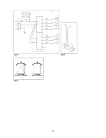
1. Disassemble the valve body by loosening the two screws located on the body of the valve. (See Fig. 13). 
2. Extract and clean the seal cone and its housing with a rag soaked with thinners. 
3. Lightly grease the cone with a special grease. 
4. Insert the cone, moving it several times, remove it again, remove the excess grease and make sure that 
the gas passage ways are unobstructed. 
5. Replace all the pieces in reverse order and check that the valve operates correctly. 

User instructions 

WARNINGS:


Keeping appliance area clear and free from combustible materials, gasoline and other flammable 
vapors and liquid. 


Do not store dangerous or flammable material in the cabinet areas above appliance; store them in a 
safe place in order to avoid potential hazards. 

For safe use of appliance, do not use it for space heating.  
Do not use aerosol sprays in the vicinity of this appliance while it is in operation 

For description of hotplates refer to installation instructions. 

Using burners


A diagram is etched on the control panel above each knob which indicates which burner corresponds to that 
knob. 

Manual ignition:


Manual ignition is always possible even when the power is cut off or in the event of prolonged power failure. 
Turn the knob that corresponds to the burner selected counterclockwise to the MAXIMUM position at the 
etched star (large flame) and place a lit match up to the burner. 

Automatic electric ignition:


Turn the knob that corresponds to the burner selected counterclockwise to the MAXIMUM position at the 
etched star (large flame) and then press the knob down to activate the spark ignition. Release the knob 
some second after the burner has ignited. 

Burners fitted with a safety device (thermocouple):


Turn the knob that corresponds to the burner selected counterclockwise to the MAXIMUM position at the 
etched star (large flame) and then press the knob down to activate the spark ignition. Once ignited, keep 
pressing the knob for about 10 seconds to allow the flame to heat the thermocouple. If the burner does not 
remain alight after releasing the knob repeat the above procedure, 

Note:

 It is recommended not to try to ignite the burner if the relative flame cap is not in the correct position 

Tips for using burners correctly: 

WARNING: During use of each gas burner(s) adjust the burner flame size properly so it does not 
extend beyond the edge of the cooking utensil. This is an instruction based on safety considerations


Summary of Contents for B3W0..U4X2D

Page 1: ...o not touch any electrical switch Do not use any phone in your building Immediately call your gas supplier from a neighbor s phone Follow the gas supplier s instructions If you cannot reach your gas suppliers call the fire department Installation and service must be performed by a qualified installer service agency or the gas supplier Read this instruction booklet before installing and using the a...

Page 2: ...en moving the cooktop The pressure regulator has female pipe thread You will need to determine the fitting required depending on the size of your gas supply line the flexible metal connector and the shutoff valve The appliance when installed must be electrically grounded in accordance with local codes or in the absence of local codes with the National Electrical Code ANSI NFPA 70 The appliance and...

Page 3: ...aust fans shall be installed in accordance with the manufacturer s instructions However in no case shall the clearance between the top of the highest burner of the cooking appliance and the range hood be less than 30 762mm See Fig 1 2 Any other downward facing combustible surface less than 600mm above the top of the highest burner shall be protected for the full width and depth of the cooking surf...

Page 4: ... WHEN CONNECTING THE SUPPLY DO NOT OVER TIGHTEN The regulated pressure For NG is 4 w c See Fig 5 6 For gas inlet position of appliance refer Fig 5 and 6 After installing the gas supply and making all connections check thoroughly for possible leaks Turn all control knobs on the unit to OFF position Open the valve on the gas supply Using a soap and water solution check each gas connection one at the...

Page 5: ...and unscrew the nozzles Fig 7 using an adjustable spanner of 7 mm and change the nozzles with those designed for the new gas supply according to the information given in TABLE A shown below TABLE A Adapting to different types of gas Drop in cooktop with 5 workyop burners model B3W0 U4X 2 or 5 D Burner Position Inj size Gas Pressure Max Rate Min Rate By pass size 1 100mm Type i w c BTU h W BTU h W ...

Page 6: ...hite plastic piece screwed under the above mentioned metal stopper afterward screw it again in opposite way under the metal stopper for gas reference see the written LP and NAT with relative indicating arrows on the white piece 3 Screw again by hand the metal stopper in the original position on the regulator Operating in this way the gas regulator is converted for use with the other gas pressure D...

Page 7: ...g Do not use aerosol sprays in the vicinity of this appliance while it is in operation For description of hotplates refer to installation instructions Using burners A diagram is etched on the control panel above each knob which indicates which burner corresponds to that knob Manual ignition Manual ignition is always possible even when the power is cut off or in the event of prolonged power failure...

Page 8: ...inuous use of the appliance may require additional ventilation for example by opening a window or increasing the power of the mechanical exhaust fan range hood if installed Cleaning the appliance Never use abrasive cleaners Before cleaning the appliance it should be disconnected from the power supply Cleaning the work surface periodically clean the burner heads the enamelled steel pan supports and...

Page 9: ...e service Dealer Importer Name address phone MANUFACTURER BERTAZZONI SPA VIA PALAZZINA 8 42016 GUASTALLA REGGIO E ITALY Tel 0522 226411 telefax 0522 226440 http www bertazzoni italia com SERVICE CENTERS Name Phone ...

Page 10: ...ez aucun interrupteur électrique N utilisez aucun téléphone dans votre établissement Appelez immédiatement votre fournisseur de gaz par le téléphone d un voisin Suivez les instructions du fournisseur de gaz Si vous ne pouvez pas atteindre vos fournisseurs de gaz appelez les pompiers L installation et le service doivent être exécutés par un installateur qualifié une agence de service ou par le four...

Page 11: ... ou CGA de 1 5 mètres de longueur maximum I D recommandé pour le branchement de cette table de cuisson au conduit d amenée des gaz Ne pliez pas ou n endommagez pas le connecteur flexible en déplaçant la table de cuisson Le régulateur de pression a un filetage au pas du gaz femelle de Vous devrez déterminer le raccordement demandé selon la dimension du conduit d amenée des gaz du connecteur en méta...

Page 12: ...eure du banc de travail mesures relatives selon la Fig 1 2 Exigences 1 Distances des meubles suspendus Valeurs minimum Les distances minimum devront être conformes aux valeurs minimum indiquées dans la table n 1 et sont illustrées dans la fig 1 2 Les hottes de cuisine et les ventilateurs aspirant doivent être installés selon les instructions du fabricant Cependant dans aucun cas la distance entre ...

Page 13: ... est de 4 colonne d eau Voir Fig 5 6 Pour la position d entrée du gaz de l appareil référez vous à la Fig 5 et 6 Après avoir installé l alimentation du gaz et après avoir effectué tous les branchements contrôlez soigneusement les éventuelles fuites Tournez tous les boutons de commande de l unité sur la position OFF Ouvrez la valve sur l alimentation du gaz En utilisant une solution avec du savon e...

Page 14: ...becs Fig 7 en employant une clé réglable de 7 mm et changez les becs avec ceux conçus pour la nouvelle alimentation de gaz selon les informations fournies dans le TABLEAU A ci dessous TABLEAU A Adaptation aux différents types de gaz Modèle B3W0 U4X 2 or 5 D Brûleur Position Diam inj Gaz Pressure Dèbit nom Dèbit reduit By pass size 1 100mm Type i w c BTU h W BTU h W 1 100mm Auxiliaire Frontale D 0 ...

Page 15: ...pérations suivantes 1 Dévisser à la main le bouchon en plastique supérieur du régulateur Fig 5 2 Dévisser à la main la pièce en plastique blanche vissée sous le bouchon en métal susmentionné ensuite le visser encore dans le sens opposé sous le bouchon en métal pour la référence du gaz voir l écriture LP et NAT avec les flèches relatives sur la partie blanche 3 Visser encore à la main le bouchon en...

Page 16: ...encore enlevez la graisse excessive et assurez vous que les passages du gaz ne soient pas obstrués 5 Replacez toutes les parties dans l ordre contraire et vérifiez que la valve fonctionne correctement Instructions pour l utilisateur ATTENTION Maintenir la zone de l appareil propre et libre des matériaux combustibles de l essence et d autres vapeurs et liquides inflammables Ne stockez aucun matérie...

Page 17: ...mocouple de sécurité peuvent seulement être allumés lorsque le bouton est en position de MAXIMUM gravure de flamme large Avertissement L utilisation d un appareil de cuisson à gaz produit de la chaleur et de l humidité dans la chambre où il est installé Par conséquent une ventilation appropriée dans la chambre est nécessaire ainsi que les ouvertures normales de ventilation qui doivent être sans ob...

Page 18: ... vente Revendeur Importateur Nom adresse téléphone FABRICANT BERTAZZONI SPA VIA PALAZZINA 8 42016 GUASTALLA REGGIO E ITALY Tél 0522 226411 fax 0522 226440 http www bertazzoni italia com CENTRES DE SERVICE Nom Téléphone ...

Page 19: ...19 Fig 1 Fig 2 Fig 3 Fig 4 Fig 5 Inches mm A 11 13 16 300 B 1 9 16 40 C 2 14 16 73 D 1 8 22 E 2 2 12 55 ...

Page 20: ...20 Fig 6 Fig 7 Fig 8 Fig 9 Fig 10 Fig 11 ...

Page 21: ...21 Fig 12 Fig 13 Fig 14 ...

Page 22: ...NNE 1 1 702 408058 ADAPTER FOR WOK BURNER PAN SUPPORT ADAPTATEUR COURONNE 1 1 723 411099 GASKET GARNITURE 6 7 760 510507 SMALL BURNER COUPE BRULEUR PETIT 1 1 761 510508 SEMI RAPID BURNER COUPE BRULEUR MOYEN 2 3 762 510509 RAPID BURNER COUPE BRULEUR RAPID 1 1 764 510511 DUAL BURNER COUPE BRULEUR CORONNE 1 1 884 502174 GAS VALVE BY PASS029 MICRO FOR IGNITION ROBINET BP029 2 2 885 502175 GAS VALVE BY...

Page 23: ......

Page 24: ......

Page 25: ......

Reviews: