English - 6
Stroke Rate Preselection
The required stroke rate can be preselected (also
during operation) using the thumbwheel 4.
1 – 2 = low stroke rate
3 – 4 = medium stroke rate
5 – 6 = high stroke rate
The required stroke rate is dependent on the ma-
terial and the working conditions and can be de-
termined by a practical trial.
After working for longer periods at low stroke rate
allow the machine to cool down by running it at
maximum stroke rate and no-load for approx.
3 minutes.
Contact Protector
The contact protector 16 attached to the housing
prevents unintentional contact with the saw blade
while working and should not be removed.
Sawdust Blower Device
The sawdust blower device leads an air jet to the
saw blade. The air jet keeps sawdust from cover-
ing the cutting line during operation.
The air flow can be switched on or off with the
switch for the sawdust blowing device 9:
Blower effect switched on:
For working with wood, plastic and
similar materials that produce large
amounts of sawdust.
Blower effect switched off:
For working with metals and with
use of coolant/lubricant as well as
when using dust/chip extraction.
The four pendulum action settings
allow optimum adaptation of cutting
speed, cutting capacity and cutting
pattern to the material being
sawed.
The pendulum action can be adjusted in four
steps with the adjustment lever 10. Switching is
possible with the machine running:
Step 0:
No pendulum action
Step I:
Small pendulum action
Step II:
Medium pendulum action
Step III:
Large pendulum action
Recommendations:
– The more narrow and clean the cutting edge
should be, the lower the pendulum action level
should be selected (or switched off).
– For thin materials, e. g. sheet metal, switch the
pendulum action off.
– For hard materials, e. g. steel, work with low
pendulum action.
– For soft materials and when sawing in the di-
rection of the grain, work with maximum pen-
dulum action.
The optimal setting can be determined by practi-
cal testing.
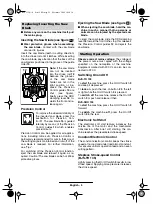
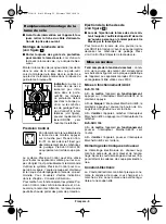
Remove the dust cover 17.
After releasing the SDS lever for
base-plate adjustment 22 and
lightly pushing back the base
plate 7, it can be tilted left or right to
a maximum of 45°.
The cutting angle can be pre-adjusted by means
of the scale for mitre angles 19. Precise adjust-
ment with use of a commercial angle gauge 20 is
recommended.
After adjusting the base plate to the 0° or 45° po-
sition, slide the base plate toward the front (direc-
tion of the saw blade) to the stop.
To lock the base plate 7, shut the SDS lever for
base-plate adjustment 22.
With the thumbwheel for pre-tension of the base
plate 21, the pre-tension of the SDS lever for
base-plate adjustment 22 can be adjusted. If the
base plate 7 is not seated tightly after shutting the
SDS lever, release the SDS lever 22 and rotate
the thumbwheel for pre-tension of the base
plate 21 in the “+” direction.
If the base plate 7 can not be adjusted or only
with difficulty after releasing the SDS lever for
base-plate adjustment 22, rotate the thumbwheel
for pre-tension of the base plate 21 in the “–” di-
rection.
For sawing close to edges, the base plate can be
offset to the rear:
Remove the dust cover 17.
Release the SDS lever for base-plate adjust-
ment 22 and slide the base plate toward the rear
to the stop.
Pendulum Action Setting
Adjusting the Cutting Angle
(see figure
)
Offsetting the Base Plate
(see figure
)
C
D
BJS 135.book Seite 6 Montag, 15. November 2004 10:10 10


