background image

Alignment with the vehicle 

Positioning 

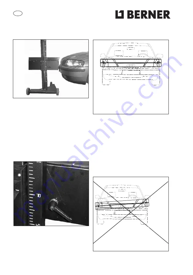
Place the headlight beam tester in front
of the right headlight of the car at a di-
stance of approx. 20cm, measure the
height from the ground to the centre of
the headlight and adjust the optical box
to the corresponding height using the
graduated scale on the column. Use the
top of the sliding block as an index on
the scale. 

GB

Adjustment  

Check that the optical box is level by
checking the spirit-level inside it. If it is
not level, loosen the lever in the picture
and adjust the box. 

Alignment  with the mirror visor 

Look for two symmetrical details on the
front of the vehicle (such as the top of
the windscreen or the headlights them-
selves). Make sure that the line on the
visor coincides with the two points of re-
ference, if not rotate the headlight beam
tester until they do. In the M version -
use the handle to rotate the headlight
beam tester. 

OK

NEIN

NO

OK

22

Summary of Contents for 047894

Page 1: ...Bedienungsanleitung Bedienungsanleitung Artikelnummer 47894 Sprachen en de BERNER_Bedienungsanleitung_Bedienungsanleitung_42265 PDF _de pdf 2016 09 23 ...

Page 2: ...Bedienungsanleitung Operating Manual Scheinwerfer Einstellgerät Headlight BeamTester 047894 D GB ...

Page 3: ...folgreich eingesetzt werden kann wenn es ordnungsgemäß benutzt und angemessen gewar tet wird Die vorliegenden Anweisungen müssen daher aufmerksam gelesen werden und zudem stets zum Nachlesen zur Verfügung stehen falls während des Gebrauchs des Geräts Schwierigkeiten auftreten sollten Bei Bedarf bieten unsere Fachhändler in Zusammenarbeit mit den Kundendienstzentren natürlich gern umfassende Bera t...

Page 4: ...en Optikkasten Spiegelvisier Grundplatte Handgriff Säule mit Gleitvorrichtung Jedes Geräteteil ist noch einmal separat verpackt Es dürfen niemals mehr als zwei Verpackungen über einander gestapelt werden Das Gewicht des Geräts beträgt 30 kg Die Abmessungen lauten wie folgt B 630 mm L 1720 mm H 310 mm Auspacken des Geräts Die Verpackung von oben öffnen und die Geräteteile entnehmen Die Verpackung f...

Page 5: ... Grundplatte G Handgriff Option B Säule H Laufrollen C Verstellvorrichtung I Feststellschrauben für Grundplatte D Spiegelvisier L Zubehör zur Befestigung des Optikkastens E Optikkasten M Staubhülle Option F Federabdeckung D ...

Page 6: ...t Farbbereichen Ablesen der Leuchtstärke in Lux über die Farbskala Bei Fahrzeugen bis zu max 40 km h und Motorrädern befindet sich die Nadel im Bereich BAD GOOD Bei Fahrzeugen über 40 km h befindet sich die Nadel im Berich GOOD Bei Ha logen und Xenon Scheinwerfern befin det sich die Nadel im Bereich HALOGEN Zum Überprüfen der Lichtstärke den Lichtschalter auf Abblendlicht stellen und die Leuchtkra...

Page 7: ... bei laufendem Fahrzeugmotor vorzunehmen ist muss eine angemessene Abgasabsauganlage bereitgestellt werden Die versehentliche Einatmung von Kohlenoxid kann den menschlichen Organis mus schwer schädigen und in manchen Fällen fatale Folgen haben Bei Kontakt aufnahme mit unserem Gebietsvertreter erhalten Sie umfassende Informationen über die für Ihren Betrieb am besten geeignete Absauganlage Das Sche...

Page 8: ...heibe 8 x 24 sowie dem einrasthebel M 8 x 20 be festigen Montage des Spiegelvisiers Das Spiegelvisier wurde während der Abnahme beim Hersteller genau für das jeweilige Gerät kalibriert und darf daher nicht in andere Scheinwerfer Einstellge räte eingebaut werden Das Visier an die Halterungsplatte annähern bis sowohl die Befestigungsbohrungen als auch die äußeren Ränder genau übereinander lie gen un...

Page 9: ...ng den Motor fünf Minuten vor Beginn der Überprüfung starten und den Vorgang bei laufendem Motor durchführen ACHTUNG Wenn in geschlossenen Räumen bei laufendem Motor gearbeitet wird müssen die schädlichen Verbrennungsgase unbedingt abgeführt werden Wir empfehlen den Einsatz spezifischer Abgas Absauganlagen Arbeitsbereich Die Überprüfung der Scheinwerfer ist auf einer ebenen Fläche vorzunehmen Soll...

Page 10: ...stens über die darin befindliche Wasser waage Libelle überprüfen Sollte diese Anzeige nicht horizontal sein den in der Abbildung sichtbaren Hebel lösen und den Optikkasten regulieren Ausrichtung mit Spiegelvisier Als Bezugspunkte vorn am Fahrzeug zwei symmetrisch angeordnete Details suchen z B den oberen Bereich der Windschutzscheibe oder die Scheinwer fer selbst Sicherstellen dass die Linie des V...

Page 11: ...ablesen Scheinwerferprüfung Einstellung vorgegebene Neigungsmaß ablesen z B 1 2 und das hinten am Optikkasten befindliche Rädchen dementsprechend drehen Sollten keine Herstellerangaben vorliegen die geltenden gesetzlichen Vor schriften beachten ACHTUNG Das Einstellmaß der Scheinwerfer muss in jedem Fall den geltenden Gesetzen entsprechen d h Scheinwerfer für Abblendlicht mit einer Höhe über der St...

Page 12: ...ung nicht besonders gekennzeichnet ist ist wie folgt zu verfahren Bei Fahrzeugen bei denen sich das Lichtbündel mit zunehmender Beladung hebt ist die Einstellung in der Endstellung der Verstelleinrichtung vorzunehmen bei der das Lichtbündel am höchsten ist Bei Fahrzeugen bei denen sich das Lichtbündel mit zunehmender Beladung senkt ist die Einstellung in der Endstellung der Verstelleinrichtung vor...

Page 13: ...f bis 1h sowie 2 und 3 der Tabelle 10 cm nach oben und 5 cm nach unten Der Knick zwischen dem horizontalen und dem ansteigenden Teil der Hell Dunkel Grenze darf nicht mehr als 5 cm von der vertikalen durch die Zentralmarke nach rechts oder links abweichen Scheinwerferprüfung und einstellung nach STZVO Bei Fahrzeugen deren Scheinwerfer von Hand verstellt werden können muss sich die Verstelleinricht...

Page 14: ...spurige Kraftfahrzeuge e Lastkraftwagen mit vorn liegender Ladefläche f Lastkraftwagen mit hinten liegender Ladefläche g Sattelzugmaschinen h Kraftomnibusse 2 Kraftfahrzeuge bei denen der höch ste Punkt der leuchtenden Fläche der Scheinwerfer höher als 140 cm über der Standfläche liegt 3 Einachsige Zug oder Arbeitsma schinen mit dauerabgeblendeten Scheinwerfern auf denen die erfor derliche Neigung...

Page 15: ... werden ACHTUNG Keine Nitro Lösungsmittel verwenden Demontage und Entsorgung Das Gerät besteht überwiegend aus Stahl Außerdem vorhandene Materialien Kunststoff einige Bauteile Papier und Karton die Verpackung sowie die zum Gerät gehörenden Unterlagen Lackierung des Geräts kratzfeste Epoxidpulver beschichtung Bei der Entsorgung des Geräts ist gemäß den vor Ort geltenden behördlichen Bestimmungen zu...

Page 16: ... properly and efficiently if used correctly and kept fully efficient We therefore request that you carefully read this instruction booklet and refer to it every time any difficulties should arise when using the device In case of need we would like to remind you that our service centres organised jointly with our retailers are always willing to provide any advice required NOTE for the purpo ses of ...

Page 17: ...s own special box divided into three parts Optical box mirror visor Base handle Column complete with sliding mechanism Not more than two boxes should be piled on top of each other The weight is 30 kg The measurements of the boxes are B 630 mm L 1720 mm H 310 mm How to unpack the appliance Open the top end of the box and pull out the parts Keep the box for possible trans port requirements GB ...

Page 18: ...ies for attaching the optical box E Optical box M Dust cover optional F Spring cover Description The headlight beam tester is a device for testing the headlights of all types of motor vehicles cars and heavy goods vehicles in general Pointing device with mirror visor The appliance can be mobile and is provi ded with a base fitted onto rubber castors GB ...

Page 19: ...ed and one of which is coloured Reading the light itensity in Lux on the color scale For vehicles up to max 40 km h and mo rorcycles is the needle in the BAD GOOD For verhicles over 40 km h is the needle in GOOD With halogen and xenon headlights is the needle in the HALOGEN To check the light itensity Light switch to low beam Illuminating read on the display Reading the light intensity in Lux Acco...

Page 20: ...ust fumes extraction system since the headlights must be tested with the engine on Accidental inhalation of carbon monoxide can cause serious injury and even prove fatal Contact our area representative to find out which is the best system for your premises Avoid leaving the headlight beam tester exposed to sunlight or in the immediate vicinity of sources of heat such as stoves radiators etc Do not...

Page 21: ... 20 screws top left and with washer 8 x 24 bigger and snap lever M 8 x 20 bottom right Fitting the mirror visor The mirror visor is calibrated with the re spective device during the testing phase and consequently cannot be used with other headlight beam testers Place the visor beside the plate so that the attach ment holes and external rims coincide screw on using the two screws provi ded Do not f...

Page 22: ...ngine five minutes before starting the test and continue with the engine on WARNING When working in enclosed areas with the engine on an extraction sy stem for the noxious fumes produced is required Use of a specific ex haust fume extraction system is recommended Work surface During testing of the headlights the floor surface must be flat If this is not possible the headlight beam tester and the v...

Page 23: ...x on the scale GB Adjustment Check that the optical box is level by checking the spirit level inside it If it is not level loosen the lever in the picture and adjust the box Alignment with the mirror visor Look for two symmetrical details on the front of the vehicle such as the top of the windscreen or the headlights them selves Make sure that the line on the visor coincides with the two points of...

Page 24: ...ht inclination given by the manu facturer e g 1 2 turn the wheel situa ted at the back of the optical box accordingly Should no indications be given by the manufacturer observe the current legal dispositions WARNING We remind you that the inclination of the headlights must in any case comply with current legisla tion which states that for lower beam headlights situated at up to 80 cm from the grou...

Page 25: ...tion For headlights with an adjustment device of only two positions meaning that the rest position is not indicated proceed as follows for vehicles on which the beam of light moves upwards the setting should be made in the final position where the beam of light is at the highest for vehicles on which the beam of light moves downwards the setting should be made in the final position where the beam ...

Page 26: ...to 10 cm upwards or downwards The division between the horizontal and upright part of the dark light barrier should not deviate by more than 5 cm from the vertical through the central stencil towards the left or right Verification and adjustment of the headlight in compliance with STVZO In vehicles on which the headlights can be positioned manually the adjustment lever should be in the rest positi...

Page 27: ...hicles e lorries with front load f lorries with back load g engines h delivery vehicles 2 Vehicles for which the highest point of the illuminated area is higher than 140 cm above the positioning surface 3 Engines and split axle work vehicles with constant lower beam headlights on which the inclination needed for the centring of the beam of light is indicated the properties of this device are to be...

Page 28: ... water and spirit or normal detergent WARNING Do not use nitrogen based solvents Demolition and disposal The appliance is made mainly of steel Other parts Plastic some small parts Cardboard and paper packaging and documents Painting of the machine epoxy scratch resistant powder For disposal of the machine observe local council regulations GB ...

Page 29: ...209 68 10 11 F Irrtümer und technische Änderungen vorbehalten 28 www berner eu ...

Reviews: