


10
11
3
coMMissioninG of positioner control
3.1
Description
controls are used for valve class III modulating and is operating with 0-20mA, 4-20mA or 0-10V
input signals.
control board allows an accurate positioning (<2%).
The dead band can be set to adjust the accuracy of the positioning.
A potentiometer is always built-in with the board in order to provide a position feedback signal.
3.2
notes reGarDinG the electrical connections
The is driven by an analogue signal and supplies an
output signal for remote position indication.
The signal cables have to be of a shielded type and be separa-
ted from power supply wires (1-inch distance min.). Otherwise
interference may occur.
The cable shield must be connected to terminal 71 and isolated
from the earth. If motorised valve setting has not already been
done by the valve supplier, please proceed as stated below.
3.3
confiGuration
Different operating parameters are adjustable thanks to switches located on the circuit board.
3.3.1
selection of positioninG operation
Two switches located on the printed circuit board are used to select the “positioning” mode:
- Switches 5 and 6 positioned on B
3.3.2
selection of input-output siGnals
Switches 1,2,3 and 4 allow to set the types of input-output signals.
3.3.3
Motor Direction of rotation
The switch 7 allows to set the direction of rotation :
- Switch 7 in A position: closing in clockwise direction.
- Switch 7 in B position: closing in counter clockwise direction.Switches (on printed circuit
board) are used to set the input and output signals of mode :
3.4
stroke settinG - aDjustMent of open anD closeD positions
In order to perform the stroke setting, it is possible to remove the potentiometer. After replacing
the potentiometer, it is necessary to renew the complete remote position signal setting procedure (see next
paragraph).
Please follow the instructions given in the “Setting of mechanical stops and travel limit switches” paragraph
of the SD range instructions for start-up (ref.TMS300SD) delivered together with the actuator. The cams
to be adjusted are the black and the white one.
3.5
settinG of reMote position siGnal
3.5.1
settinG of closeD position (0%)
Drive the actuator carefully to the closed position.
Connect a milliamperemeter or a millivoltmeter on terminals 71,72.
With a screwdriver, adjust the potentiometer until reading 4mA (4-20mA signal),
0mA (0-20mA signal) or 0V (0-10V signal).
Start an actuator opening and check that the signal current/voltage increases.
3.5.2
settinG of open position (100%)
Drive the actuator carefully to the open position.
Connect a milliamperemeter or a millivoltmeter on terminals 71,72.
With a screwdriver, adjust the potentiometer until reading 20mA (0-20mA and 4-20mA signal)
or 10V (0-10V signal).
The actuator is now ready to operate following an input signal.
3.6
DeaD banD settinG
control board dead band should be adjusted only if the actuator is “hunting”.
In this case, use a small screwdriver to adjust the «Dead Band» potentiometer value until
the actuator stops and stays at the desired position.
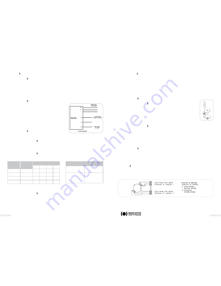
4
contacts De siGnalisation ouvert/ferMé (option)
La signalisation des positions Ouvert et Fermé est assurée par des contacts de fin de course
auxiliaires optionnels positionnés en regard des cames de couleur beige et grise du bloc à cames.
La connexion à ces contacts s’effectue aux bornes 20 à 25 comme suit :
Feedback potentiometer setting
Input signal specification
Signal
Input
impedance
0-20mA
4-20mA
0-10V
260ohm
260ohm
10kohm
Input
Signal
Output
Signal
Switches position
1
2
3
4
0 to 10V
0 to 10V
B
B
B
B
2 to 10V
2 to 10V
B
B
B
A
4 to 20mA 4 to 20mA
A
A
A
A
0 to 20mA 0 to 20mA
A
A
A
B


