background image


                    Berg Hortimotive 


2-2016 


Translated user manual  

BRW185 V3_2016 

  10/27 


5.3 

SKEWNESS INDICATOR 

 
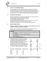
The pipe rail trolley is equipped with a skewness indicator. The indicator transmits an 
acoustic signal if the trolley exceeds a obliquity of 2°. In the latter event, all activities 
should be ceased immediately and the pipe rail system readjusted/levelled.  


1.1 The pipe rail system should be erected in such a way that the stability of the pipe rail wagons, which are designed to run on the 
rails, should never present a dangerous situation. To that end the following should be taken into account: 
a) pipe rail supports should all correspond, or at least be of the same specifications: steel base plates 1.5 mm thick with reinforcing 
sections; base plate width at least 115 mm; and long enough so that the base plates stick out a minimum of 70 mm from the two 
upright supports which carry the pipes. 
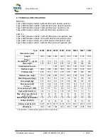
b) pipes should correspond, or at least be of the same specifications given in the table below: 


TABLE: Pipes 


Category 

Track width 
in mm 

Pipe diameter / wall 
thickness in mm 

Support distance  
in mm 

Permissible axle weigh  
in kg with St 33 

1, 2, 3, 7, 8


420 to 600  

 
Ø 51 / 2.25 

 
max 1250 

 
260 

550 to 600 

Ø 51 / 2.25 

max 1670 

220 

420 to 600 

Ø 45 / 2 

max 1000 

221 

4


420 to 600 

Ø 45 / 2 

max 1250 

177 

4


420 to 600 

Ø 38 / 2 

max 1000 

157 

4


420 to 600 

Ø 38 / 2 

max 1250 

126 

4


1


Using Steel 37 (St 37) the permissible axle weight can be raised by a factor of 1.2. 

2


The permissible axle weight depends on the length of the wheelbase of the wagon with regard to the support distances: the axle 

weight given in the table applies to pipe rail wagons with a wheelbase less than 62.5% or those greater than 125% of support 
distance.  

3

 Using wagons with a wheelbase greater than 62.5% but less than 125%


of the support distance, the permissible axle weigh may 

raised by a factor of 1.3. 

4

 The permissible axle weight is given for a track width of 420. With wider track widths the permissible axle weight is raised by the 

following correction factors: 1.08 with track width 500 mm; 1.13 with track width 550 mm; and 1.17 with track width 600 mm. 

5

 The permissible axle weight is given for a track width of 550 mm. The permissible axle weight for a track width of 600 mm may be 

raised by a 1.04 correction factor. 

6

 The track width is the centre to centre distance between the pipes. For a track width greater than 600 mm, the same permissible 

axle weight can used as for 600 mm. 

7

 If a smaller support distance is used than shown in the table above, then the permissible axle weight may be higher than given: 

the correction factor is changed in proportion to the reduction in the support distance. 

8

 Using pipe rail wagons with an axle weight greater than shown in the table is only permitted if it is clear that the wheel pressure in 

unfavourable load conditions is no greater than 75% of the loading level where the rails begin to buckle, and for no more than 5 
mm from the original; and the carrying capacity of the pipe rail support is not exceeded (according to item 1.1, a) with respect to the 
foundation; that being a load of 300 kg.   


Fig. 5.1; Chapter 1.1 of Article 1 of Policy Regulation 3.2; Pipe Rail Systems in 

Greenhouses Working Conditions Act (10-02-2004).


Summary of Contents for BRW 170

Page 1: ...22407 single scissors hydraulic lift wheels operation pole BRW 170 Type 22410 double scissors hydraulic lift wheels and operation pole Type 22420 double scissors manual lift wheels and operation pole...

Page 2: ...on 8 5 PUTTING INTO OPERATION 9 5 1 Inspection before use 9 5 2 Minimum requirements for pipe rail system horticulture industry directives 9 5 3 Skewness indicator 10 6 APPLICATION 11 6 1 Operation 12...

Page 3: ...e rail trolley appear to malfunction or have defects 1 3 WARRANTY For a period of 6 months after delivery Berg Hortimotive gives the client a warranty on material and manufacturing defects that occur...

Page 4: ...em directives for the horticulture industry outlined in paragraph 5 2 Only use the Pipe Rail Trolley on a suitable pipe rail system Check if the centre to centre dimension ctc of the trolley matches t...

Page 5: ...ver who have received adequate training with regard to the trolley and who have studied the contents of this manual The pipe rail trolley should only be operated if positioned correctly on the pipe ra...

Page 6: ...batteries see maintenance Always stand beside the lift bar if the trolley is raised by using the manual lift system for sideways movements Hold the bar with one hand while moving the trolley Disconnec...

Page 7: ...to aid the nurture maintenance or harvest of crops plants Do not use the pipe rail trolley for applications other than those described The trolley is designed to carry one person and loose goods with...

Page 8: ...Place the fork of the forklift in the middle under the chassis of the pipe rail trolley Before lifting with the forklift verify that the fork is correctly positioned under the pipe rail trolley in ord...

Page 9: ...fy the most recent requirements of the horticultural sector guidelines for pipe rail systems Figure 5 1 provides the minimum requirements for the pipe rail system which have been taken from the hortic...

Page 10: ...wagon with regard to the support distances the axle weight given in the table applies to pipe rail wagons with a wheelbase less than 62 5 or those greater than 125 of support distance 3 Using wagons w...

Page 11: ...extended period of time Charge the batteries at least twice a week Less frequent charging will reduce the capacity of the batteries and the lifetime of the batteries the motor and the drive control CA...

Page 12: ...maximum height release the push button to prevent unnecessary excess pressure in the lift cylinders The platform raises as long as the button is pushed EMERGENCY STOP SWITCH 3 Push in to stop Turn rig...

Page 13: ...O LOWER THE OPERATING PLATFORM 7 Use this pressure switch to lower the operating platform The platform will lower as long as the button is pushed Beware of any persons or obstacles near the scissors R...

Page 14: ...moved sideways When equipped with hydraulic lifting wheels see explanation above nr 2 and 7 Always hold the lever with one hand during sideways transportation Push the Trolley with the other hand Bew...

Page 15: ...elease emergency stop and turnkey switch on Foot switch is defect Replace foot switch The foot switch s cable is broken Replace cable Reversing switch is faulty Consult your dealer The carbon brushes...

Page 16: ...Translated user manual BRW170 BRW185 V3_2016 16 27 Problem C Difficulties regulating speed Cause Speed regulator is not properly secured Solution Secure button Operation printed circuit board is faul...

Page 17: ...mechanical damage Charge batteries and check level of distilled water in batteries Clean wheels and chain Remove wind up rope and leaves Check whether lifting lowering movements runs smoothly low hyd...

Page 18: ...hain and chain wheels All maintenance should be noted in the maintenance logbook appendix 7 3 BATTERY MAINTENANCE Charge the batteries at least twice a week with a suitable charger Prevent the batteri...

Page 19: ...ng connect the negative cable last CAUTION Always connect the positive red to the positive pole and negative blue to the negative pole Battery fluid is a corrosive acid prevent contact with clothes sk...

Page 20: ...istance 1 mm 115 115 115 115 115 115 115 115 Step height 400 530 530 400 700 700 590 590 Height operation pole 1250 1250 1250 1250 1250 1250 Platform length 1800 1800 1800 1800 1500 1500 1500 1500 Pla...

Page 21: ...ted user manual BRW170 BRW185 V3_2016 21 27 APPENDIX I MAINTENANCE LOGBOOK Please outline repairs and or maintenance carried out on the form below Date Description of repair maintenance pipe rail trol...

Page 22: ...he level of speed as closely as possible to the work tempo potentiometer If the speed is set optimally fewer stops and starts are required which has a very positive effect on the wear of the pipe rail...

Page 23: ...red to the positive pole and the negative terminal black to the negative pole on the battery Battery fluid is corrosive avoid contact with clothing skin and eyes Wash battery acid splashes on clothing...

Page 24: ...Berg Hortimotive 2 2016 Translated user manual BRW170 BRW185 V3_2016 24 27...

Page 25: ...Berg Hortimotive 2 2016 Translated user manual BRW170 BRW185 V3_2016 25 27 Return the old batteries to your supplier or municipal waste disposal department when replacing them with new...

Page 26: ...r use Dullness or contamination on the top layer periodically after detection How to clean Remove dirt or contamination on the top layer using a soft brush or cloth or a compressed air line 6 bar Chem...

Page 27: ...Serial nr meets the stipulations of the most recent 98 37 EC Equipment Directive subsequently modified to 98 79 EG and additionally satisfies the latest versions of the following EC directives Electr...

Reviews: