background image

PART No.  DESCRIPTION  . . . . . . . . . . . . . .QTY

1

COMPUTER . . . . . . . . . . . . . . . . . . . . 

MASTER PARTS & ACCESSORY LIST

Some of the above accessories
are pre-fitted to the master
component. They may not be
supplied separately

Note

2

HANDLEBAR FOAM  . . . . . . . . . . . . . 

3

HAND PULSE CABLE . . . . . . . . . . . . 

4

HAND PULSE PADS . . . . . . . . . . . .

5

HANDLEBAR . . . . . . . . . . . . . . . . . . . 

6

UPPER HANDLEBAR (L+R) . . . . . . . .

7

END CAP . . . . . . . . . . . . . . . . . . . . .  

8

UPPER HANDLEBAR FOAM (L+R) . . .

1

1SET

2

2

9

M8 x 15mm ALLEN BOLT . . . . . . . . . . . 

10

M8 SPRING WASHER . . . . . . . . . . . .

11

M8 CURVED WASHER . . . . . . . . . . . .

12

LOWER HANDLEBAR (L+R) . . . . . . . 

13

BUSHING . . . . . . . . . . . . . . . . . . . . . . 

14

LOWER HANDLEBAR COVER . . . . . . . 

15

FOOT SUPPORT COVER . . . . . . . . . . .

16

M6 x 50mm CARRIAGE BOLT . . . . . . 

4
2SET

2SET

4

8

18

18

1SET

17

FOOTPLATE (L+R) . . . . . . . . . . . . . . .

18

CHAIN COVER (L+R) . . . . . . . . . . . . 

19

CRACK END CAP . . . . . . . . . . . . . . . 

20

M8 x 20mm COATED ALLEN BOLT . . .

21

ROUND COVER . . . . . . . . . . . . . . . . . . 

22

CRANK . . . . . . . . . . . . . . . . . . . . . .

23

REAR END CAP . . . . . . . . . . . . . . . .

24

M8 x 75mm CARRIAGE BOLT . . . . . . 

2

2

2

4

25

REAR SUPPORT . . . . . . . . . . . . . . . . . 

26

WATER BOTTLE . . . . . . . . . . . . . . . . 

27 M8 x 

80

mm BOLT . . . . . . . . . . . . . . .

28

FOOTPLATE SUPPORT BAR (L+R) . . . 

29

M10 FLAT WASHER . . . . . . . . . . . . . . 

30

M10 NYLON LOCK NUT . . . . . . . . . . .

31

M6 FLAT WASHER . . . . . . . . . . . . . . 

32

M6 SPRING WASHER . . . . . . . . . . . .

2

2
4

4

1
1

2
1SET

1SET

1SET

2

33

FOOT ADJUSTMENT KNOB . . . . . . . . .

34

M8 x 20mm COATED ALLEN BOLT . . . 

4

35

M8 x 16 FLAT WASHER . . . . . . . . . . . . 

36

M8 x 48mm ALLEN BOLT . . . . . . . . . .

37

FOOT SUPPORT PIVOT BRACKET BUSH

38

M8 FLAT WASHER . . . . . . . . . . . . . . .

39

M8 NYLON LOCK NUT . . . . . . . . . . . . .

40

M15 CURVED WASHER . . . . . . . . . . 

41

BOLT . . . . . . . . . . . . . . . . . . . . . . . .  

42

FLYWHEEL BEARING . . . . . . . . . . . . 

2

2

1

4

43

TUBE SPACER . . . . . . . . . . . . . . . . . . 

44

MAINS ADAPTOR SOCKET & LEAD . . .

45

MAIN FRAME . . . . . . . . . . . . . . . . . .

46

SENSOR SCREW . . . . . . . . . . . . . . .

1

1

1
1

2

2

4

4

47

SENSOR SET . . . . . . . . . . . . . . . . . . .

48

SCREW . . . . . . . . . . . . . . . . . . . . . . 

49

LOWER COMPUTER LINK CABLE . . . .

50

WAVE WASHER . . . . . . . . . . . . . . . . 

51

DRIVE WHEEL . . . . . . . . . . . . . . . . . .

52

DRIVE WHEEL SHAFT . . . . . . . . . . . . 

53

BOLT . . . . . . . . . . . . . . . . . . . . . . . .  

54

M5 x 15 SCREW . . . . . . . . . . . . . . . 

1

1

3

8

55

M5 x 15 SCREW . . . . . . . . . . . . . . . .

56

M4.5 x 25 SELF TAPPING SCREW . . .

57

PLASTIC COVER . . . . . . . . . . . . . . . .

58

M5 x 10 SCREW . . . . . . . . . . . . . . . 

59

FOOT HOLDER BRACKET . . . . . . . . . . 

60

M5 x 15 SCREW . . . . . . . . . . . . . . .  

61

PLASTIC END CAP . . . . . . . . . . . . . . 

62

HANDLEBAR PIVOT BUSH . . . . . . . . .

2

2

2

6

6

6

1

4

63

3/8'' NUT . . . . . . . . . . . . . . . . . . . . . . 

64

3/8'' WASHER . . . . . . . . . . . . . . . . . 

65

BELT ADJUSTMENT SET . . . . . . . . . . 

66

DRIVE BELT . . . . . . . . . . . . . . . . . . . 

67

FLYWHEEL . . . . . . . . . . . . . . . . . . . .

68

FRONT END CAP . . . . . . . . . . . . . . . 

69

FRONT SUPPORT . . . . . . . . . . . . . . . 

70

M8 DOME NUT . . . . . . . . . . . . . . . . . 

1

2

1

4

71

MOTOR . . . . . . . . . . . . . . . . . . . . . . .

72

LOWER FRONT COVER . . . . . . . . . . . 

73

RUBBER RING . . . . . . . . . . . . . . . . .  

74

UPPER COMPUTER LINK CABLE . . . . 

1

1

1

1

1

1

2
1

1

4

2

2

2

75

M8 x 20mm ALLEN BOLT . . . . . . . . . 

76

HANDLEBAR POST . . . . . . . . . . . . . . . 1

6

77

M5 x 15mm SCREW . . . . . . . . . . . . . 

78

BOTTLE HOLDER . . . . . . . . . . . . . . . . 

10

1

79

ROTATION ROD . . . . . . . . . . . . . . . . .

84

ALLEN KEY WRENCH . . . . . . . . . . . . .

85

COMBINATION WRENCH . . . . . . . . . .

80

CENTRE PLASTIC COVER . . . . . . . . . .

82

PLASTIC SPACER (L+R) . . . . . . . . . . . 1SET

1

2

1

1SET

83

PLASTIC COVER . . . . . . . . . . . . . . . .

86

ADAPTOR . . . . . . . . . . . . . . . . . . . . . .  1

1SET

81 SCREW . . . . . . . . . . . . . . . . . . . . . . 

4

6

1

1

1SET
1SET

Assembly & Adjustments

Page 23

07PME 

Programmable

 Magnetic Elliptical Trainer

Summary of Contents for 07PME

Page 1: ...bly User Manual 07PME Programmable Magnetic Elliptical Trainer Please ensure that you read this manual carefully before attempting to assemble or use your new Beny Sports product and retain for future...
Page 2: ......

Page 3: ...Contents Section Page General Information 4 Before you start 5 Safety 6 Exercise Information 7 Assembly and Adjustments 14...

Page 4: ...Y for a period of 1 YEAR from the original certified date of purchase During this period we have the right to a Provide parts for the purchaser to effect repair b Repair the product returned to our wa...

Page 5: ...staples that may be used to fasten the flaps as these may cause injury Be sure to open the carton the right way up as this will be the easiest and safest way to remove all the components Unpack the C...

Page 6: ...wear or damage Clean only with a damp cloth do not use solvent cleaners If you are in any doubt do not use your product but contact CUSTOMER SUPPORT by any of the means listed on the opposite page Bef...

Page 7: ...y your heart With regular exercise your cardiovascular system will become stronger and more efficient Your recovery rate i e the time taken for your heart to reach its normal resting level will also d...

Page 8: ...your heart is working in its exercise target zone you need to be able to take your pulse If you do not have a pulse monitor either from the product you are using or a proprietary independent unit you...

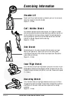
Page 9: ...n Exercises Hold each stretch for a minimum of ten seconds and then relax Repeat each stretch two or three times Do this before your Aerobic Exercise session and also after you have finished Head Roll...

Page 10: ...retch Open both arms to the side and gently lift them above your head Reach your right arm as high as you can for one count gently stretching the muscles of the stomach and lower back Repeat the actio...

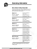
Page 11: ...5 10 Minutes Cool Down 5 Minutes Exercise 4 minutes at A Rest 1 minute Exercise 2 minutes at A Exercise slowly 1 minute Exercise 5 minutes at A Rest 1 minute Exercise 3 minutes at A Exercise slowly 2...

Page 12: ...Exercise Notes Use this space to record your own exercise routine results...

Page 13: ...Exercise Notes Use this space to record your own exercise routine results...

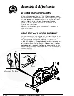
Page 14: ...the leaflet supplied with the Exercise Monitor for all operational functions DRIVE BELT and FLYWHEEL ALIGNMENT It may be necessary at some stage to adjust the Drive Belt 66 on your Programmable Magnet...

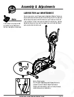
Page 15: ...lean the metal and plastic components a general household cleaner can be used but please be sure to dry the trainer and any attachments before use In the interest of safety do NOT use polish or any lu...

Page 16: ...following accessories are supplied in a pack and should be checked before attempting assembly Item 38 Qty 4 Item 75 Qty 6 Item 11 Qty 14 Item 10 Qty 14 Item 81 Qty 4 Item 77 Qty 10 Item 34 Qty 4 Item...

Page 17: ...assembly of your product PLEASE NOTE that some of the parts may be pre fitted to major components so please check carefully before contacting our CUSTOMER SUPPORT team In any event please do not retu...

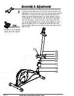
Page 18: ...and Curved Washers 11 from the Main Frame and lower the Handlebar Post 76 into position Loosely re fit the 6 x M8 x 20mm Allen Bolt 75 6 x M8 Spring Washers 10 6 x M8 Curved Washers 11 and align the...

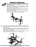
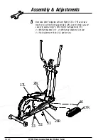
Page 19: ...dlebar Post 76 as shown below 3 12L 12R 38 61 76 34 79 6L 9 11 80 82 83 10 12L 15 27 28L 34 35 77 28R 12R 29 30 76 22 22 10 Now attach the Footplate Support Bars 28L 28R by sliding them onto the Crank...

Page 20: ...hem on top of the Foot Support Bars 28 Line the holes up and secure in place using 4 x M6 x 50mm Carriage Bolts 16 4 x M6 Flat Washers 31 4 x M6 Spring Washers 32 and 4 x Foot Adjustment Knob 33 tight...

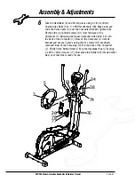
Page 21: ...Now plug the Upper Computer Link Cable 74 into the back of the Computer 1 Now sit the Computer 1 onto its bracket and secure in place using the 4 x screws 81 previously removed Now fit the Pulse plug...

Page 22: ...6 48 50 51 52 53 54 57 77 28 R 17 R 12 R 67 66 65 64 68 69 71 49 72 73 74 63 47 59 8 R 58 60 10 11 12 L 13 14 16 17 L 15 20 23 24 25 26 27 28 L 29 30 39 44 55 56 18 R 61 62 79 34 38 6 R 75 76 78 I t e...

Page 23: ...4 35 M8 x 16 FLAT WASHER 36 M8 x 48mm ALLEN BOLT 37 FOOT SUPPORT PIVOT BRACKET BUSH 38 M8 FLAT WASHER 39 M8 NYLON LOCK NUT 40 M15 CURVED WASHER 41 BOLT 42 FLYWHEEL BEARING 2 2 1 4 43 TUBE SPACER 44 M...

Page 24: ...y The Crossings Cross Hills West Yorkshire BD20 7BW CUSTOMER SUPPORT is open from 9 00am to 5 00pm from Monday to Friday Tel 0871 222 0881 Fax 01535 637722 E mail support benysports co uk Copyright Be...

Reviews: