background image

20

Bentone  

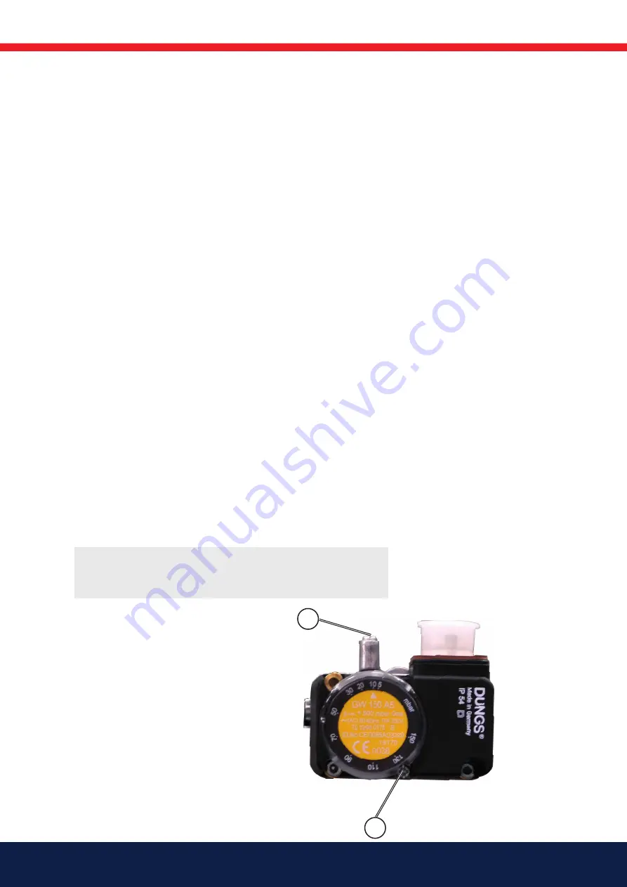
5.4  Setting the min. gas pressure 

switch

The min. gas pressure switch should react to a burner connection pressure 
that is too low and in such cases prevent the burner from starting. If the 
connection pressure to the burner is too low during operation, the min. gas 
pressure switch should stop the burner. The burner can start again once 
the connection pressure has risen above the pressure set for the min. gas 
pressure switch.

Setting for min. gas pressure switch

1. 

Remove the protective cover, screw (Y).

2. 

Open the pressure outlet (X) and connect a manometer to measure the 
connection pressure.

3. 

Start the burner.

4. 

Measure and make a note of the connection pressure to the burner 
during normal operation at the highest input power.

5. 

Based on the desired connection pressure set, determine the 
connection pressure at which the gas pressure switch should stop the 
burner. Set the connection pressure at which the burner is stopped at 
a level where the burner is stopped before poor combustion occurs. 

6. 

Set the min. gas pressure switch to this value by turning the scale.

7. 

Check the setting by carefully closing the ball valve while measuring the 
connection pressure.

8. 

When the min. gas pressure switch stops the burner, the value 
measured should then approximately correspond to the setting on the 
min. gas pressure switch. The tolerance on the scale for the min. gas 
pressure switch is approx. ±15%.

9. 

Open the ball valve.

10.  Remove the pressure gauge and close the pressure outlet (X).  

11.  Fit the protective cover, screw (Y).

!

Check the gas tightness.

X

Y

Summary of Contents for BG400M

Page 1: ...Providing sustainable energy solutions worldwide CR00264 178 114 74 2 2021 06 16 Installation and maintenance instruction BG 400 M LME22 233C2 MB VEF 407 CF Translation of the original instructions ...

Page 2: ...oaded at www bentone com ecodesign da 1 Manualer på andre sprog 2 www bentone com download eller scan QR koden 3 Indtast brænderens artikelnummer der findes på typeskiltet se billede og vælg dit sprog Detaljerede oplysninger om ecodesign kan downloades på www bentone com ecodesign fr 1 Manuels dans d autres langues 2 www bentone com download ou scannez le code QR 3 Saisir le numéro d article du br...

Page 3: ...Gas nozzle______________________________________ 15 4 9 Setting Damper motor modulating operation ________ 16 5 Setting the burner ___________________________________ 17 5 1 Adjustment of brake plate _________________________ 17 5 2 Control of burner head____________________________ 17 5 3 Setting the air pressure switch _____________________ 19 5 4 Setting the min gas pressure switch ____________...

Page 4: ...a dry environment max 80 relative humidity no condensation Temperature 20 to 60 C Check that the burner is compatible with the boiler s output range All components must be installed without being bent twisted or subjected to mechanical or thermal forces which can affect the components The burner must be installed so that it complies with local regulations for fire safety electrical safety and fuel...

Page 5: ... be put into operation without proper safety and protection devices A Class BE fire extinguisher is recommended It is forbidden to alter thedesign or use accessories which have not been approved by Enertech in writing Prior to operation the following points must be checked fitting and installation work has been completed and approved electrical installation has been correctly performed flue gas du...

Page 6: ...check 1 year 3 000 hrs Filter 1 year replacement at Δp 10 mbar 3 000 hrs replacement at Δp 10 mbar Electrodes Replacement Cleaning 1 year Replacement Cleaning 3 000 hrs Brake disc Replacement Cleaning 1 year Replacement Cleaning 3 000 hrs Motor 1 year 3 000 hrs Fan wheel 1 Year Replacement when cleaning needed imbalance 3 000 hrs Replacement when cleaning needed imbalance The burner and its compon...

Page 7: ... Technical data Burners are intended for use at Hot water boilers in intermittent operation 2 1 Dimensions Gas connection 3 4 2 K L M H øC A F I E D øB G J 2 1 1 Heat generator connection dimensions The above dimensions are max measurements Depending on the components used the measurements may vary Min recommended distance to floor Dimensions when installing blast tubes from the inside of the boil...

Page 8: ...r see data plate 1 Lower heat value Hu at normal state 15 C and 1013 25 mbar EN676 Grade of gas Natural gas Natural gas Butane Propane Gas quantity and capacity vary according to grade of gas and connection pressure BG 400 2 BG 400 M G20 61 325 6 4 34 2 360 G25 61 310 7 4 37 8 360 G30 61 350 1 9 10 5 360 G31 61 340 2 5 14 2 360 kWh Nm3 MJ Nm3 kcal Nm3 G20 9 5 34 02 8126 G25 8 2 29 25 6986 G30 32 5...

Page 9: ...el can be reduced by connecting the burner s air intake to the air duct that opens into an appropriate location Installation must be done so it does not prevent air supply to the burner 2 4 Working field BG 400 2 BG 400 M Type BG 400 Motor 250W 230V 1 7A 50Hz The recommended main fuse motor C10A Control power 230V 2 2A 50Hz Sound 85 dBA 0 5 dBA 1 0 1 2 3 4 5 6 7 8 50 100 150 200 250 300 350 mbar k...

Page 10: ...per motor 7 Inner assembly adjustment not for town gas 8 Flame cone 9 Multibloc 10 Connecting pipe 11 Air damper 12 Air intake 13 Gas pressure switch 14 Ball valve 15 Electrical panel 16 Fan wheel 17 Electrical connection 18 Motor 19 Ignition electrode 20 Transformer 21 Ionization electrode 22 Inner assembly 23 Nozzle 24 Brake plate ...

Page 11: ...ion and maintenance The unit must be serviced and maintained at the interval specified in the service schedule If the burner is in a dirty environment service should be done at more frequent intervals than specified 3 5 Start up After the burner has been fitted to the boiler and the electric connection the leakage control the venting and the electric function test have been carried out the burner ...

Page 12: ...icated gas pressure 3 The gas supply system should be installed in accordance with current standards 4 Pipe lines should be run so that service on boiler and burner is facilitated 5 Pipe lines should be run so that eventual contaminants cannot come into contact with the gas components 6 Gas discharge system must be installed prior to local regulations 4 4 Electric connection Before starting the el...

Page 13: ...i bloc Loosen the union nut Removal of fan house unit from burner Remove the screws A Swing out the fan housing Remove the ionisation and ignition wires from the electrodes Remove the bolt B on the spectacle flange Lift away the fan housing Installation example Connect the gas to the burner by means of the ball valve Ensure that the union nut ball valve and tubing make it easy to remove the burner...

Page 14: ...d be 1 5x max inlet pressure or min 150 mbar If any leakage locate the source by means of soapy water or a leak location spray After tightening repeat the test Electric function test Ensure that phase and neutral are not reversed The gas shut off cock should be closed To prevent the gas pressure switch from locking out it should be linked temporarily After the main switch has been switched on and ...

Page 15: ...15 Bentone 172 515 08 2018 01 02 4 8 Gas nozzle Natural gas Propan Biogas UV detector 2 5 8 0 ...

Page 16: ...n MIN and if mounted gas pressure switch max in position MAX Start burner If no flame is formed and the manometer does not give a reading adjust the amount of gas by increasing with screw N on the multi block Check combustion values Set high load by pressing control switch increase Adjust the amount of gas with screw V on the multi block and check the combustion values Return to low load check com...

Page 17: ...e plate affects the air flow It is therefore always necessary to make a fine adjustment of the air by means of the adjustment device of the burner 5 2 Control of burner head To check the burner head brake plate and electrodes proceed as follows Loosen the nuts a Swing out the burner Remove the screw b and the knob for adjustment of burner head Loosen the screw c so much so that the inner assembly ...

Page 18: ...e main switch If the burner starts the actual adjustment can be made Adjustment of burner head The burner is equipped with an adjustment device changing the position of the brake plate in the burner head This is used to adjust the correct pressure drop over the combustion device in order to obtain a good pulsation free combustion Which position to use depends on input and overpressure in the boile...

Page 19: ...tch clockwise until the air pressure switch stops the burner Is the tolerance on the scale for the min air pressure switch approx 15 4 Try to find the pressure at which the burner stops for both the minimum and maximum input power by turning the scale Make a note of the values and then set the air pressure switch on the basis of the highest pressure noted at which the burner stopped 5 The air pres...

Page 20: ...to the burner during normal operation at the highest input power 5 Based on the desired connection pressure set determine the connection pressure at which the gas pressure switch should stop the burner Set the connection pressure at which the burner is stopped at a level where the burner is stopped before poor combustion occurs 6 Set the min gas pressure switch to this value by turning the scale 7...

Page 21: ...h mini 5b Gas pressure switch maxi 6a Main valve 2 stage When modulaing operation is required this valve is equipped with controls for variable opening 6b Safety valve 7 1 Valve proving system 9 Air pressure switch 10 Gas burner control Pos 5b 7 Components not required according to EN 676 1 Required over 1200 kW according to EN 676 hhh MultiBloc ...

Page 22: ...ion 1 8 before V1 before governor 10 Adjustment screw for zero point adjustment N min load 11 Test point connection 1 8 PF 12 Test point connection 1 8 PBr 13 Flange connection outlet 14 Test point connection 1 8 Pa before V2 after governor 15 Indication of V1 and V2 in operation not standard 16 O ring Check the filter at least once a year It is possible to connect a leakage control VPS 504 and a ...

Page 23: ... lines should preferably be made of steel Inside diametre ø 4 mm steel tube ø 6 4 For PL other material can be used Impulse lines PL and PBR are ready from factory Impulse lines shall be mounted in such a way that no conden sate can flow back into the multibloc This is especially important when PF is concerned Impulse lines shall be mounted in such a way that they are protected against rupture and...

Page 24: ...DN p p a p a Br F pL 3 p e 3 p e 7 8 4 6 1 5 1 3 3 4 2 2 6 8 7 6 5 5 Pressure taps P1 L1 Mp N P1 L1 MP N 2 1 S 10 S 30 1 3 4 5 G 1 8 screwed sealing plug 2 Measuring nozzle 6 7 8 G 1 8 female thread for pL pF pBr pulse lines 6 5 6 Electrical connection ...

Page 25: ...gas 6 0 21 60 5159 6 1 Recommended excess air when using default setting Grade of gas Excess air flue gases Max CO2 O2 CO2 Lambda 1 2 Natural gas 3 5 10 11 9 Propane 3 5 11 5 13 9 Butane 3 5 11 5 14 1 Biogas 3 5 6 2 Determining the gas quantity for the system The heat values indicated are normal values the heat value varies according to the origin of the gas For more exact information on values co...

Page 26: ...19 Nm3 h Hu η 9 5 0 90 Example C V 0C Q 160 19 Nm3 h Hu 0 00116 η 8126 0 00116 0 90 If the barometer reading altitude pressure and temperature of the gas deviate significantly from normal values this must be taken into account as follows Calculation example Q 160 kW HU Example A 34020 MJ Nm3 Example B 9 5 kWh Nm3 Example C 8126 kcal Nm3 η 90 V0 Desired quantity of gas Nm3 h Q Boiler output kW HU G...

Page 27: ...sually to measure how long it takes for the burner to consume a certain quantity of gas To measure t Time for a certain quantity of gas consumed by the burner h M Quantity of gas consumed m3 V Actual gas flow m3 h V V0 f VA V0A f 18 8 0 90 17 m3 h VB V0B f 19 0 90 17 m3 h VC V0C f 19 0 90 17 m3 h This means that the quantity of gas read from the gas meter should actually be read off as 1 11 the ca...

Page 28: ...ain power supply and disconnect the Euro plugs from the burner 2 Remove the screws A turn off the burner Remove the ignition and ionisation cables 3 Check the combustion device s position Remove the screw B to remove the adjustment device 4 Remove the screw C remove the combustion device 5 Check and clean the brake plate and gas inlet If necessary replace the worn parts 6 Check the ignition electr...

Page 29: ...ate 9 Remove the damper motor from the mounting plate I 10 Install the new damper motor on the mounting plate 11 Mount the damper to the damper motor s shaft Ensure that the screw is perpendicular to the plane of the shaft 12 Re install the damper motor and mounting plate on the air intake Ensure that the damper shaft and control arm are connected correctly 13 Connect the damper motor cable 14 Fit...

Page 30: ...30 Bentone 7 3 Principle sketch of a 3 way solenoid valve 7 4 Continuous fan operation P R A 0 1 Auto Brown Blue S8 S8 Power supply off Power supply on 172 615 26 2018 02 14 ...

Page 31: ...s made easier by the fact that all gas burners are equipped with a divisible ionisation cable The reason for low ionisation current can be leakage current poor connection to earth fouling or incorrectly positioned ionisation electrode in the combustion head Occasionally an incorrect gas air mix may result in poor ionisation current Technical data For continuous operation Idle voltage at ION termin...

Page 32: ...ry only if a malfunction is suspected 7 5 3 Flame monitoring UV detector QRC Technical data For continuous operation Idle voltage at ION terminals AC 115 230V Protect the ionisation electrode from electric shock Short circuit current Max AC 100 300 mA Max current for flame detection Max DC 5 5 µA Required current to ensure detection Min DC 40 µA Possible detection current Max DC 60 µA Operational ...

Page 33: ...ndent on three factors electricity gas and air supply Should there be any changes in the ratio between these three factors there is a risk of break downs It has been proved that most break downs are caused by simple faults Before calling the service engineer the following should therefore be checked Is the gas cock open Are all fuses in order and the current switched on Are the thermostats correct...

Page 34: ...s burner are installed in to Se local regulations for information Safety system cables must be run in separate cables outgoing signal must not come in same cable as incoming signal Signals must be in different harnesses for safety reasons Safety system as door switches water level pressure temperature and other safety limiters must be installed in safety loop according to process 172 615 65 2 ...

Page 35: ...35 Bentone 10 2 Wiring diagram LME ...

Page 36: ...noid valve 1 V3 Solenoid valve 3 Y4 Solenoid valve air 10 3 Function LME 1 Operating switch ON Thermostat ON Gas pressure switch ON A check that the air pressure switch does not indicate fan pressure is carried out 2 Burner motor starts A check that the air pressure switch indicates sufficient fan pressure is carried out 3 The ignition spark is created 4 The gas solenoid valve is open The gas is i...

Page 37: ...king red Interface diagnostics Red flicking 10 4 1 1 Diagnosing alarm causes After alarm disconnection the red alarm signal light is lit continuously The diagnosing of the alarm cause can be read according to the following sequence Continuous Off Red Yellow Green 10 4 1 2 Limiting of starting repetitions LME 11 has a function with start repetition if the flame is not created at start or disappears...

Page 38: ...lves defective or fouled flame monitoring Flashing 8 x Free Flashing 9 x Free Flashing 10 x Connection fault or internal fault outgoing contacts or other faults Flashing 14 x CPI contact not closed During the diagnosing of the alarm cause the control outputs are voltage free The burner is disconnected Exception alarm signal AL at board 10 Reconnection of the burner happens after resetting only Pre...

Page 39: ...otor faulty Burner control faulty Replace Burner motor running no ignition spark at the end of pre aeration No power in the terminals Check the connector Replace faulty burner controls Ignition electrodes in contact with each other or earth Adjust Ignition electrode porcelain damaged Replace the electrodes Poor connection to cable connectors Adjust connection Ignition cables damaged Replace Transf...

Page 40: ...djust Gas pressure too high Check and adjust using pressure gauge and pressure control valve Flue gas side blocked Check the chimney flue Burner pulsates during operation Burner incorrectly set Adjust Burner dirty Clean the burner Incorrect chimney Check and modify dimensions if necessary Burner functioning properly but with occasional blockage Ionisation current too low Check Must be at least 6 µ...

Page 41: ...supply Check flue gas damper Holes in gas nozzle clogged Clean Poor fresh air intake Check and increase Flame at incorrect angle due to combustion head out of position Check the combustion head and readjust Condensation build up in boiler and chimney Flue gas temperature too low or gas volume too low Raise the flue gas temperature by increasing gas volume Insulate the chimney ...

Page 42: ...ermostats etc are correctly adjusted 10 Read the instructions and follow the directions given for the burner as to starting up and service 12 4 2 Maintenance 1 Switch off the current with the main switch 2 Shut off the gas supply with the shut off cock on the burner Normal operation 1 Ensure that the air supply to the burner is not obstructed by dust and dirt 2 Have the installer make a yearly ove...

Page 43: ...Measu rement C µ A Before After mbar mbar Small Flame Large Flame Measures Date Nm3 gas h Governor CO2 CO Fluegas temp Ionisation current Pressure Efficiency Fire room Chimney Measu rement C µ A Before After mbar mbar Small Flame Large Flame Measures Date Nm3 gas h Governor CO2 CO Fluegas temp Ionisation current Pressure Efficiency Fire room Chimney Measu rement C µ A Before After mbar mbar Small ...

Page 44: ......

Page 45: ......

Page 46: ......

Page 47: ......

Page 48: ...Enertech AB P O Box 309 SE 341 26 Ljungby www bentone com ...

Reviews: