


16
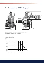
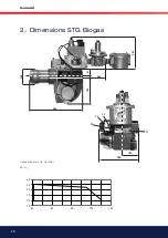
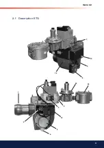
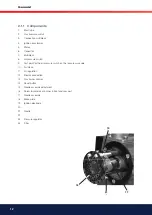
General
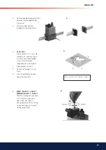
7.
8.
9.
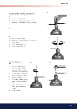
7.
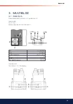
DMV-DLE Rapid stroke adjustment V start Factory setting
DMV-DLE:
Rapid stroke not adjusted
1.
Unscrew the adjustment cap E from the hydraulic brake.
2.
Turn the adjustment cap and use as a tool.
3.
Turn a-clockwise = increase rapid stroke (+).
8.
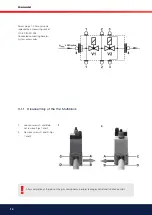
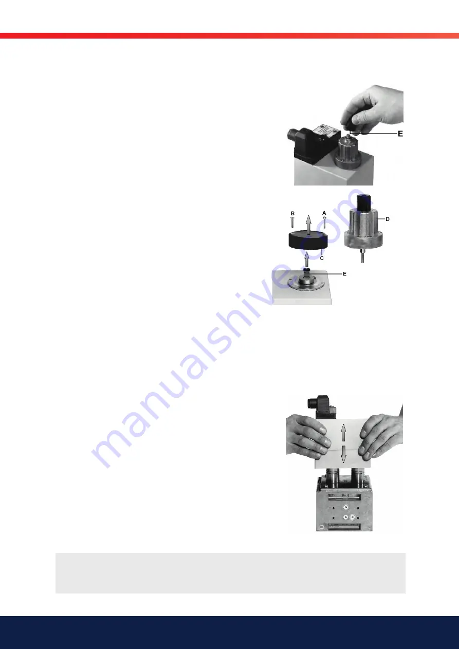
Replacing hydraulic brake unit or adjustment plate
1.
Switch off firing system.
2.
Remove locking varnish from countersunk screw A.
3.
Unscrew countersunkscrew A.
4.
Unscrew socket headscrew B.
5.
Raise adjustment plate C or hy-draulic brake D.
6.
Remove sealing plug E
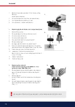
7.
Exchange adjustment plate C or hydraulic brake D
8.
Screw in countersunk and socket head screw. Only tighten
socket head screw so that hydraulic brake can just be turned.
9.
Coat countersunk screw A with locking varnish.
10. Leakage test: Pressure tap at sealing plug 2:
DMV 507-520/11 Pressure tap at sealing plug 3: DMV 525/11
p max. = 500 mbar.
11. Perform functional test.
12. Switch on firing system.
9.
Replacing the solenoid
Versions with adjusting plate DMV-D 5.../11or
hydraulic brake DMV-DLE 5../11
1.
Remove hydraulic brake or adjusting plate as described on
page 6: ”Replacing the hydraulic brake or adjusting disk”,
steps 1 - 5.
2.
Replace solenoid
Important: Make sure that the solenoid no. and voltage are
correct!
3.
Remount hydraulic brake or adjusting plate as described on
page 6. ”Replacing the hydraulic brake or adjusting plate”,
steps 7 -11.
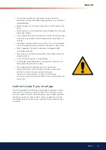
!
After completion of the jobs on the gas components, perform leakage control and function control.
Summary of Contents for BFG1
Page 2: ......
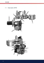
Page 8: ...8 General 1 1 Description BFG1 7 8 10 11 12 13 14 15 16 22 1 2 3 4 5 6 24 23...
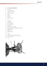
Page 11: ...11 General 7 8 10 9 1 2 3 5 6 12 4 2 1 Description STG 23 24 16...
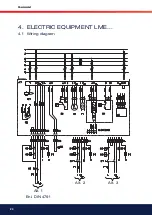
Page 20: ...20 General 4 ELECTRIC EQUIPMENT LME 4 1 Wiring diagram Alt 1 Enl DIN 4791 Alt 2 Alt 3...
Page 24: ...24 General...
Page 25: ...25 General...
Page 26: ...26 General...
Page 27: ......
Page 28: ...Enertech AB P O Box 309 SE 341 26 Ljungby www bentone se www bentone com...


