background image

Network connection

31

Network connection

Connecting to a LAN

To set the display to connect to a local area network: 
1. Connect a RJ45 cable to the corresponding ports on the display and your LAN 

switch or router. 

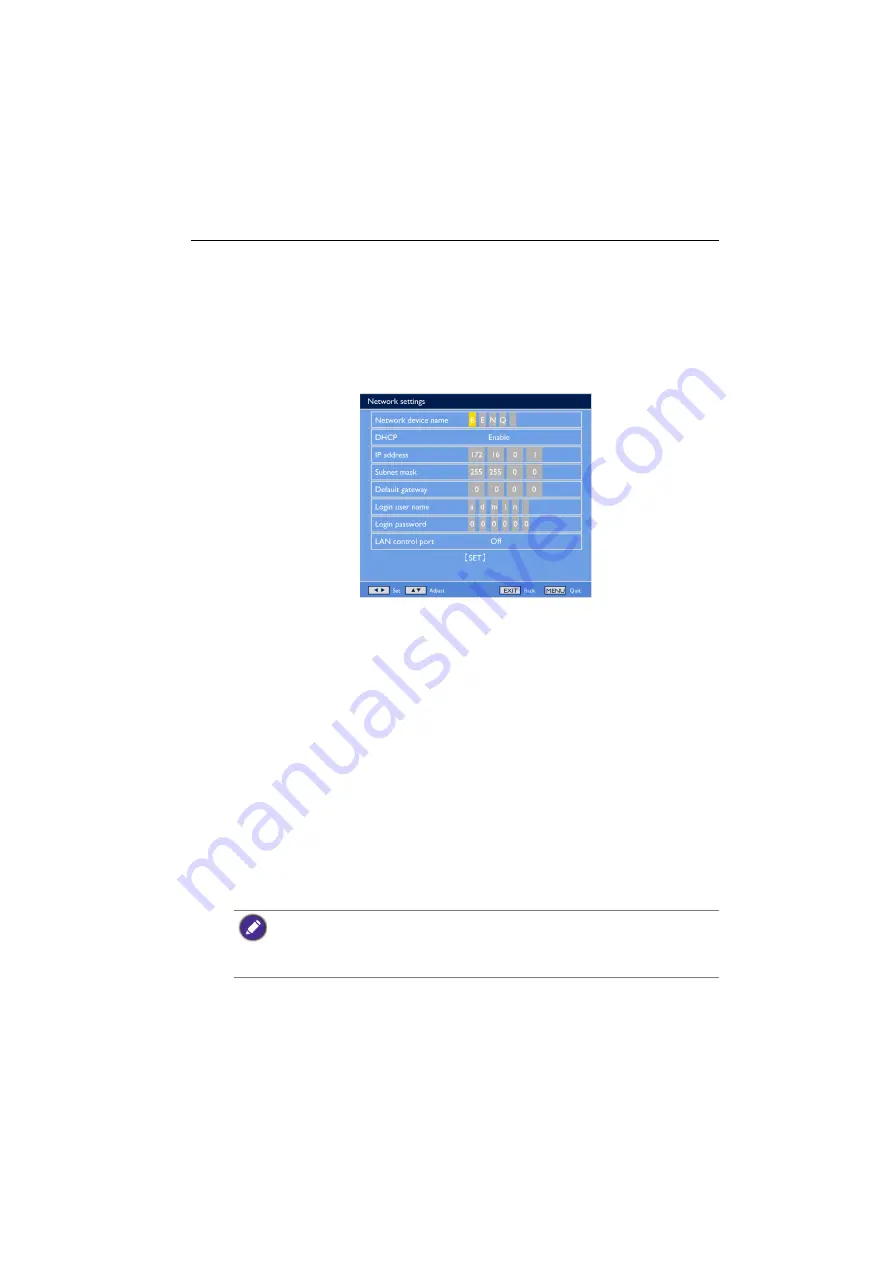
2. Enter the OSD menu 

Configuration1

 > 

Network settings

. You will see the OSD 

page similar to the following picture.

3. Use the 

/

/

/

 buttons to set the 

Network device name

.

4. If you are in a DHCP environment, highlight 

DHCP

 and select 

Enable

. Once 

selected, the 

IP address

Subnet mask

, and 

Default gateway

 settings will be 

displayed. 

If you are not in a DHCP environment, highlight 

DHCP

 and select 

Disable

Contact your ITS administrator for information on the 

IP address

Subnet mask

and 

Default gateway

 settings and enter it accordingly.

5. Make sure the information on the 

Login user name

 is displayed.

6. Use the 

/

/

/

 buttons to set 

Login password

. The password is required 

when using a computer browser to log in.

7. To control the display with a computer browser, highlight 

LAN control port

 and 

select 

On.

8. To save the settings and return to the previous menu, highlight 

SET

 and press the 

SET

 button on the remote control.

Controlling the display

Once you have the correct IP address for your display and the display is on or in standby 

mode, you can use any computer that is on the same local area network to control the 

display.

• You cannot control the display via the RS-232C connector when LAN control is in use.
• Currently most browsers are supported. However, if using Internet Explorer, only versions 7.0 

or higher are supported.

• The screen shots in this manual are for reference only, and may differ from what is displayed on 

your screen.

Summary of Contents for TL650

Page 1: ...TL650 Interactive Flat Panel User Manual...

Page 2: ...ontents thereof without obligation to notify any person of such revision or changes Copyright Copyright 2012 BenQ Corporation All rights reserved No part of this publication may be reproduced transmit...

Page 3: ...rminals 12 Remote control 14 Using the remote control 15 Setting up the display 16 Mounting the display 16 Connecting audio video signals 18 Connecting the touch module 24 Connecting power 25 Using th...

Page 4: ...SD menu 36 Picture menu 37 Screen menu 39 Audio menu 42 Configuration1 menu 43 Configuration2 menu 45 Option menu 46 Update menu 49 Product information 50 Dimensions 50 Specifications 51 Supported inp...

Page 5: ...Using wrong or unsuitable accessories may cause the display to fall and result in serious personal injuries Make sure that the surface and fixing points are strong enough to sustain the weight of the...

Page 6: ...ms or when unused for long periods of time 14 Refer all servicing to qualified service personnel Servicing is required when the apparatus has been damaged in any way such as power supply cord or plug...

Page 7: ...bject between the remote control and the remote sensor of the product When the remote control will not be used for an extended period remove the batteries Battery safety notice The use of the wrong ty...

Page 8: ...ent and standards pertaining to environmental management BenQ has spared no efforts in pushing our initiatives further to incorporate life cycle design in the aspects of material selection manufacturi...

Page 9: ...y LCD display Power cord D Sub 15 pin cable Remote control AAA batteries Quick start guide CD USB cable Touch pen x 2 The type of power cord supplied may differ from that illustrated depending on your...

Page 10: ...ls from the remote control Detects ambient lighting conditions around the display and adjusts screen brightness automatically when the Ambient Light Sensor function is activated Indicates the operatin...

Page 11: ...he OSD menu Returns to a previous menu or exits the OSD menu Scrolls through settings and options in the OSD menu Power button Turns on the display or puts it in standby mode Power indicator Indicates...

Page 12: ...D player HDTV device or Laser disc player VGA OUT Outputs analog RGB signals from the VGA IN to another display VGA IN Receives analog RGB signals from an external device such as a computer DVI D OUT...

Page 13: ...IO3 Receives audio signals from an external device such as a VCR or DVD player AC SWITCH ON OFF Turns on or off the main power AC IN Connects to a power outlet via the supplied power cord AC OUT Relay...

Page 14: ...lution VGA Selects the VGA input source DVI Selects the DVI input source Power Turns on the display or puts it in standby mode EXIT Returns to a previous menu or closes the OSD menu ENTER Confirms you...

Page 15: ...ong light the remote control may not operate properly In this situation change the light source readjust the angle of the display or operate the remote control from a location closer to display s remo...

Page 16: ...horizontal and object free surface Make sure that the size of the cloth is larger than the display 2 Gently lay the display on the cloth with the LCD screen facing down 3 Remove the desktop stands fr...

Page 17: ...facturer accepts no liability for installations not performed by a professional technician 1 Place a clean dry and lint free cloth on a flat horizontal and object free surface Make sure that the size...

Page 18: ...e cable itself Always grasp and pull the connectors at the end of the cable Ensure that all cables are fully inserted and firmly seated Connecting the VGA input 1 Connect the VGA IN jack on the displa...

Page 19: ...splay using an HDMI cable or a DVI D to HDMI conversion cable 2 Connect the computer s audio output jack to the AUDIO IN AUDIO1 jack on the display using a suitable audio cable 3 To view video image f...

Page 20: ...s a VCR or DVD player using a component video cable 2 Connect the DVD player s audio output jacks to the AUDIO IN AUDIO2 or AUDIO3 jacks on the display using a suitable audio cable 3 To view video ima...

Page 21: ...cable or Display Port to DVI VGA HDMI adaptor 2 Insert the audio cable to the AUDIO IN AUDIO1 input of the display and connect to the corresponding PC connector The cables are not supplied and should...

Page 22: ...t in amplifier on the display allows you to output audio signals through external speakers Connect external speakers to the SPEAKERS R L jacks on the display You can use the remote control or the cont...

Page 23: ...e resolution of the input signal you use This RS 232C connection requires an RS 232C port equipped computer with the display management software installed The cables except for the VGA cable are not s...

Page 24: ...he display 24 Connecting the touch module Connect the USB cable on the display to a computer The touch module supports easy Plug and Play operations There is no need to install additional drivers on t...

Page 25: ...r use with 110 240V AC power only The power cord and outlet illustrated may differ from the ones used in your region Only use an appropriate power cord for your region Never use a power cord which app...

Page 26: ...e on the display to a computer Multi touch functions are only supported by Windows 7 Home Premium Professional Enterprise and Ultimate versions For Windows XP Windows Vista and Windows 7 Starter and H...

Page 27: ...r Flick in a desired direction Multi touch functions For Windows 7 Home Premium Professional Enterprise and Ultimate versions Right click 1 Press on the target 2 Tap the screen with another finger 3 R...

Page 28: ...ons Use one finger to pivot around another Supported by specific applications Tap two fingers simultaneously The target should be the midpoint between the fingers For Windows XP Windows Vista and Wind...

Page 29: ...nnot function normally if the bars are bent Keep the touch screen out of direct sunlight or spotlights Avoid displaying still images to prevent image retention Regularly clean the retro reflective bar...

Page 30: ...MENU and for 5 seconds Once locked the display does not respond to any remote control operations unless unlocked Switching input signals Press the INPUT button on the remote control or the INPUT butt...

Page 31: ...enter it accordingly 5 Make sure the information on the Login user name is displayed 6 Use the buttons to set Login password The password is required when using a computer browser to log in 7 To contr...

Page 32: ...ou have set in the Network settings Login password menu and press Login If the password has not been set enter the default 000000 3 The setting page appears Power Setup Allows you to manage the power...

Page 33: ...me frequently used settings are provided on this page for you to control the display Tiling Setup Allows you to arrange multiple displays in a video wall or matrix and define the position of each one...

Page 34: ...t Color Color temperature Color control Light sensor DCR Picture mode Video source Picture reset 37 Screen H position V position Clock Clock phase Zoom mode Custom zoom Screen reset 39 Audio Speaker V...

Page 35: ...tion Input resolution Black level expansion Settings cloning Scan mode Scan conversion Film mode IR control IR out Keyboard control Tiling Heat status Date and time Schedule Monitor ID DDC CI HDMI CEC...

Page 36: ...Press ENTER VIDEO SOURCE to confirm selections 3 Press ENTER to confirm selections 4 Press or to select a feature and press or to adjust settings Press ENTER VIDEO SOURCE to save changes 4 Press and t...

Page 37: ...er Black level Adjust to change image brightness Noise reduction Adjust to remove the noise in the image You can select a suitable noise reduction level For Component input with interlaced video only...

Page 38: ...scenes This function is not available when Light sensor or Brightness under Panel saving is turned on Disable these functions to make DCR accessible from the OSD menu Picture mode Sets the display mo...

Page 39: ...creen Audio Configuration1 Configuration2 Option Update Name Description H position Adjusts the horizontal position of the VGA input image V position Adjusts the vertical position of the VGA input ima...

Page 40: ...produced in 4 3 format and a black band is displayed on either side of the picture Dynamic Fill the entire screen by stretching 4 3 pictures non proportionally Custom Choose to apply the custom zoom s...

Page 41: ...de is set to Custom Screen reset Resets all settings in the Screen menu Zoom Expands the horizontal and vertical sizes of the image simultaneously H zoom Expands the horizontal size of the image only...

Page 42: ...the rear connector panel Line Out Selects the audio output source from AUDIO OUT R L on the rear connector panel Internal Select the audio input source from AUDIO IN on the rear connector panel Volum...

Page 43: ...nected to a wall outlet Power off The display will remain off when the power cord is connected to a wall outlet If you unplug the power cord and re plug within 7 seconds the display will not work unde...

Page 44: ...cking It is not recommended to keep a single static image displayed on your unit for long periods of time This can cause image sticking or ghost imaging which will decrease the quality of your images...

Page 45: ...y when input signal is changed Sleep timer Sets the display to turn itself off to standby mode within a user specified amount of time Off 24 hours from current time When the Sleep timer is activated S...

Page 46: ...and HDMI video mode inputs only Settings cloning Transfers all the OSD settings between the display and a USB flash drive Scan mode Changes the display area of the image Overscan Displays about 95 of...

Page 47: ...t Enable Point the remote control to the first display which IR OUT port connects to the second display s IR IN port and the second display s IR OUT port connects to the third display s IR IN port and...

Page 48: ...le on the list will take priority Monitor ID Assigns an ID number for the current display when multiple displays are connected DDC CI Turns the DDC CI communication function On or Off HDMI CEC Uses th...

Page 49: ...om USB menu and press SET 6 Select Yes to start update A status message appears 7 After the update process completes the display will re start automatically The display does not support USB flash driv...

Page 50: ...Product information 50 Product information Dimensions Unit mm...

Page 51: ...Touch Output USB 2 0 PC Support Windows XP Vista 7 Glass Tempered glass 5 mm 0 mm 0 3 mm Input Computer VGA D Sub 15 pin Video DVI DVI D YPbPr BNC jacks HDMI HDMI jack type A DisplayPort Audio L R RCA...

Page 52: ...o F Operating Humidity 10 90 without condensation Storage Temperature 20 60o C 4 140o F Storage Humidity 10 95 without condensation Mechanical Weight kg 71 5 Dimensions W x H x D mm 1515 8 x 888 6 x 1...

Page 53: ...20 x 400 70Hz 800 x 600 60Hz 800 x 600 75Hz 1024 x 768 60Hz 1024 x 768 75Hz 1280 x 768 60Hz 1280 x 800 60Hz 1280 x 960 60Hz 1280 x 1024 60Hz 1360 x 768 60Hz 1366 x 768 60Hz 1600 x 1200 60Hz 1920 x 108...

Page 54: ...nd Check the following Have you turned on the mute function on the display or the input source device Turn off the mute function or increase the audio volume level and try again Are there any loose ca...

Page 55: ...inted at the display s remote control sensor window Check for any obstacle between the remote control and the remote control sensor window Check that the remote control sensor window is not under stro...

Reviews: