background image

Safety warnings and precautions

6

Safety warnings and precautions

• The mains plug of the power supply cord shall remain readily operable. The AC 

receptacle (mains socket outlet) shall be installed near the equipment and shall be easily 

accessible. To completely disconnect this equipment from the AC mains, disconnect the 

power cord plug from the AC receptacle.

• Do not place this display on an uneven, sloping or unstable surface (such as a trolley) 

where it may fall and cause damage to itself or others.

• Do not place this display near water, like a spa or pool, or in a position which will allow 

the splashing or spraying of water onto the display, like in front of an open window 

where rain water may enter.

• Do not install this display in a confined space without proper ventilation and air 

circulation, such as in a closed cabinet. Allow proper space around the display for 

dissipating heat inside. Do not block any openings and vents on the display. Overheating 

may result in hazards and electric shock.

• Installation of this display should only be performed by a qualified technician. Failure to 

install this display properly may cause injuries and damages to the personnels and the 

display itself. Check the installation regularly and maintain the display periodically to 

ensure the best working condition.

• Use only the accessories approved or recommended by the manufacturer to mount this 

display. Using wrong or unsuitable accessories may cause the display to fall and result in 

serious personal injuries. Make sure that the surface and fixing points are strong enough 

to sustain the weight of the display.

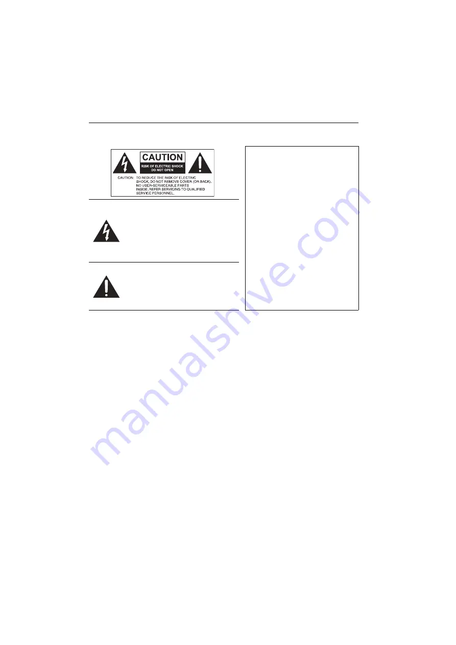
• To reduce the risk of electric shock, do not remove covers. No user serviceable parts 

inside. Refer servicing to qualified service personnel.

• To prevent personal injuries, mounting the display or installing desktop stands is 

required before use.

THIS EQUIPMENT MUST BE 

GROUNDED
To ensure safe operation, the three-pin 

plug must be inserted only into a 

standard three-pin power outlet which 

is effectively grounded through normal 

household wiring. Extension cords 

used with the equipment must have 

three cores and be correctly wired to 

provide connection to the ground. 

Wrongly wired extension cords are a 

major cause of fatalities.
The fact that the equipment operates 

satisfactorily does not imply that the 

power outlet is grounded or that the 

installation is completely safe. For your 

safety, if you are in any doubt about 

the effective grounding of the power 

outlet, please consult a qualified 

electrician.

The lightning flash with arrowhead 

symbol, within an equilateral triangle, is 

intended to alert the user to the 

presence of uninsulated “dangerous 

voltage” within the product's enclosure 

that may be of sufficient magnitude to 

constitute a risk of electric shock to 

persons.
The exclamation point within an 

equilateral triangle is intended to alert 

the user to the presence of important 

operating and maintenance (servicing) 

instructions in the literature 

accompanying the appliance.

Summary of Contents for PL4901

Page 1: ...PL4901 PL5501 PL5502 LCD Monitor User Manual...

Page 2: ...ontents thereof without obligation to notify any person of such revision or changes Copyright Copyright 2020 BenQ Corporation All rights reserved No part of this publication may be reproduced transmit...

Page 3: ...BenQ DISPLAY SUPPORT Downloads model name User Manual EU only Dismantled information Available on the user manual download page This document is provided based on Regulation EU 2019 2021 to repair or...

Page 4: ...ements for enclosure locating 12 Mounting in Portrait Position 13 Parts of the display and their functions 14 Input output terminals 14 Remote control 15 Using the remote control 16 Connection 17 IR a...

Page 5: ...ble of Contents 5 Operations RS232 29 Operations LAN 33 Troubleshooting 34 Product information 35 Specifications 35 USB device compatibility 36 Dimensions 37 Supported input signal resolution 40 1 11...

Page 6: ...Using wrong or unsuitable accessories may cause the display to fall and result in serious personal injuries Make sure that the surface and fixing points are strong enough to sustain the weight of the...

Page 7: ...on to avoid injury from tip over 13 Unplug this apparatus during lightning storms or when unused for long periods of time 14 Refer all servicing to qualified service personnel Servicing is required wh...

Page 8: ...ntrol Do not expose the remote control to water or moisture Failure to do so could result in malfunction Confirm there is no object between the remote control and the remote sensor of the product When...

Page 9: ...d standards pertaining to environmental management BenQ has spared no efforts in pushing our initiatives further to incorporate life cycle design in the aspects of material selection manufacturing pac...

Page 10: ...xtender cable x 1 RS232 IR loop cable x 1 RS232 to USB cable x 1 RJ45 to RS232 cable x 1 Alignment kit x 1 The type of power cord supplied may differ from that illustrated depending on your region of...

Page 11: ...02 600 x 400 4 M6 x 40L To mount this display to a wall you will have to obtain a standard wall mounting kit commercially available We recommend using a mounting interface that complies with TUV GS an...

Page 12: ...e weight of the display To prevent the display from falling For wall or ceiling installation we recommend installing the display with metal brackets which are commercially available For detailed insta...

Page 13: ...Setting up the display 13 Mounting in Portrait Position The display PL4901 PL5501 PL5502 can be installed in portrait position and rotated 90 degrees anticlockwise 90...

Page 14: ...upported signals from an external device DP IN Connect a video source to a display device DVI D IN DVI D video input DVI D OUT DVI D video output VGA Receive analog RGB signals from an external device...

Page 15: ...off OK Scroll through settings and options in the OSD menu Volume VOL VOL Turn up down the volume MENU Open or close the OSD menu EXIT Return key SOURCE Switch input source ID Setting Press and enter...

Page 16: ...sor window is exposed to direct sunlight or strong light the remote control may not operate properly In this situation change the light source readjust the angle of the display or operate the remote c...

Page 17: ...n Connect the LAN cable from the RS232 OUT of Display 1 to the RS232 IN of Display 2 It is for command sending and IR loop through External IR receiver Connect the IR receiver to the RS232 IN of the d...

Page 18: ...o the RS232 USB cable with computer for RS232 control Make sure the dip switch is in RS232 LAN Connect the LAN cable from the display LAN port to a router Make sure the dip switch is in LAN Connect th...

Page 19: ...onnect the DVI out of Display 1 to the DVI in of Display 2 DVI daisy chain supports up to 12 displays without splitter DVI daisy chain supports DVI HDMI 2 DP source in Display 1 Display 2 DVI OUT DVI...

Page 20: ...Connection 20 HDMI 2 IN HDMI HDMI2 IN HDMI 1 does not support DVI daisy chain...

Page 21: ...is suitable for use with 100 240V AC power only The power cord and outlet illustrated may differ from the ones used in your region Only use an appropriate power cord for your region Never use a power...

Page 22: ...ill enter standby mode Operations in the OSD menu Power Switch The display s standby mode still consumes power To completely cut off power supply set the Power switch to OFF O and then disconnect the...

Page 23: ...om Choose Custom to adjust RGB Aspect ratio Press on the remote control to select an aspect ratio Options are 16 9 or 4 3 Backlight Adjust brightness level from 0 100 Color range Full stands for 0 255...

Page 24: ...minutes Off Disable the power saving mode Power on mode On Automatically power on after connecting to the outlet Off Remain shut down after connecting to the outlet Last power status Restore users to...

Page 25: ...the USB root folder The resolution must be 1920 x 1080 and the file must be under100 KB 2 Insert the USB then click Custom logo Scene settings Scene number Switch between the selected scenes Empty Sa...

Page 26: ...ng and comparing the color characteristics of each display and then calibrating all displays with a common and optimal setting With the color calibration you can also adjust color settings of each dis...

Page 27: ...ware 27 Connect the DVI out of Display 1 to the DVI in of Display 2 DVI daisy chain supports up to 12 displays without splitter 4 Connect laptop to video walls RS232 link DVI IN DVI IN DVI DP IN DP DP...

Page 28: ...ay via RS232 USB cable and RJ45 RS232 cable Make sure the dip switch is in RS232 Connect the RS232 OUT of Display 1 to RS232 IN of Display 2 via LAN cable 5 Launch the configuration and calibration to...

Page 29: ...ting CUSTOM luminance can be changed in Custom Target xy 6 In Custom target xy users can customize target color temperature The x mark should be retained within the white rectangular box Click OK to s...

Page 30: ...color meter on the center of the target display and click Measure Record the X Y Lv value as a standard 2 Move the color meter to the next display select the corresponding Unit ID and click Get 3 Adju...

Page 31: ...wall configuration To initiate video wall circle the target displays and click Videowall on Name Description Source Display Switch input source and enable disable video wall tiling Power Backlight Tur...

Page 32: ...Color calibration video wall setup software 32 Name Description Remote Scene Edit save video wall scene and call virtual remote control...

Page 33: ...mation 2 Select LAN then click Set A search window will pop out 3 Click Start Search to scan display in the network Check the box and click Create 4 Click Connect to start LAN connection 5 Enter total...

Page 34: ...Is the display correctly connected to the computer Check if the RS232 cable can be detected in Win Device Manager If not install the driver for RS232 cable Is the display turned on Is the COM port set...

Page 35: ...80 3 Brightness cd m2 typical 500 nits Contrast typical 1200 1 Response time ms typical 8 Panel Bit 8 or 10 10 bit Aspect Ratio 16 9 Input Video VGA 1 DVI 1 HDMI 1 2 0 1 HDMI 2 1 4 1 DP 1 Audio Audio...

Page 36: ...681 2 121 1 Bezel Dimension T B L R mm PL4901 2 5 1 0 2 5 1 0 PL5501 2 3 1 2 2 3 1 2 PL5502 0 44 0 44 0 44 0 44 Feature Image setting O Source Volume Control O DVI Daisy Chain Max 12 without splitter...

Page 37: ...Product information 37 Dimensions PL4901 Unit mm 7 9 5 287 1 7 9 5 287 1 127 81 7 PP 7 7 5 02817 6 5 7 5 37 0...

Page 38: ...Product information 38 PL5501 Unit mm 287 1 287 1 7 9 5 7 9 5 127 81 7 PP 7 7 5 02817 6 5 7 5 37 0...

Page 39: ...Product information 39 PL5502 Unit mm 287 1 7 9 5 287 1 7 9 5 127 81 7 PP 7 7 5 02817 6 5 7 5 37 0...

Page 40: ...1280 720 60Hz 1280 x 768 60Hz 1280 x 960 60Hz 1280 x 1024 60Hz 1360 x 768 60Hz 1366 x 768 60Hz 1440 x 900 60Hz 1680 x 1050 60Hz 1920 x 1080 60Hz 3840 x 2160 24Hz 3840 x 2160 25Hz 3840 x 2160 30Hz 384...

Reviews: