

10/ 2004
BENNING MM 4
13
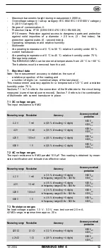
42 kΩ
10 Ω
± (0.9 % of r 4 digits)
600 V
eff
600 V
DC
420 kΩ
100 Ω
± (1.2 % of r 4 digits)
600 V
eff
600 V
DC
4,2 MΩ
1 kΩ
± (1.2 % of r 4 digits)
600 V
eff
600 V
DC
42 MΩ
10 kΩ
± (3.0 % of r 8 digits)
600 V
eff
600 V
DC
7.4 Diode testing
The stated measurement accuracy applies in the range between 0.4 V and
0.8 V.
Overload protection for diode testing: 600 V
eff
/ 600 V
DC
Measuring
range
Resolution
Accuracy
max. meas.
current
Max. no-load
voltage
0.1 mV
± (1.5 % of r 5 digits)
1,5 mA
3,3 V
7.5 Continuity testing
The integrated buzzer sounds at resistances R < 50 Ω.
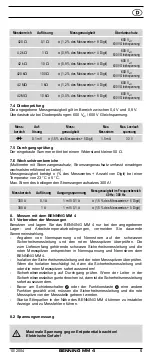
7.6 AC ranges
(Multimeter with current transducer attachment. Current transducer grips single
live conductor wire).
Measurement accuracy is ± (% of r number of digits) at a temperature
of 23 °C ± 5 °C.
Max. current of enclosed current transducer 300 A!
Measuring
range
Resolution
Output
voltage
Accuracy
300 A
0.1 A
1 mV/ 0.1 A ± (1.5 % of r 5 digits) in frequency range
40 Hz - 300 Hz
300 A
1 A
1 mV/ 0.1 A ± (1.5 % of r 5 digits) in frequency range
40 Hz - 300 Hz
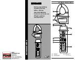
8. Measuring with the BENNING MM 4
8.1 Preparation for measurement
Store and use the BENNING MM 4 only under the correct temperature
conditions specified. Always avoid prolonged exposure to sunlight.
- Check nominal voltage and current data on the black safety test lead and red
test probe. The black test lead and the red test probes supplied correspond
to the BENNING MM 4 in nominal voltage and nominal current.
- Check insulation of the safety test lead and red test probe. If the insulation
is damaged, discard the lead and test probes immediately.
- Check the continuity of the safety test lead. If the conductor in the safety
test lead is interrupted, discard the safety test lead immediately.
- Before selecting another function at the sliding switch
2
or function button
4
, the safety test lead and red test probes must first be disconnected from
the measurement point.
- Strong sources of interference in the vicinity of the BENNING MM 4 may
cause unstable or incorrect readings.
8.2 Voltage measurement
Always observe the maximum voltage to earth potential!
Electrical hazard!
The maximum voltage which may be applied to the sockets of the Multimeter with
- COM socket
7
, marked black,
- V-Ω socket (positive)
8
for voltage and resistance measurements,
continuity and diode testing (marked red) of the BENNING MM 4 with
reference to earth potential is 600 V.
- Plug the black safety test lead into the COM socket
7
(black).
- Plug the red test probe into the V-Ω socket
8
(red).
- With the slide switch
2
, the function button
4
and the RANGE button
6
of
the BENNING MM 4, select the desired range.


