


COMMUNICATION PROTOCOL
REV: 13/05/2022
·
©2022 Benewake
(Beijing) Co., Ltd. |
| All rights reserved
BP-UM-22 A03
11
3.2.3
CAN Bus Network
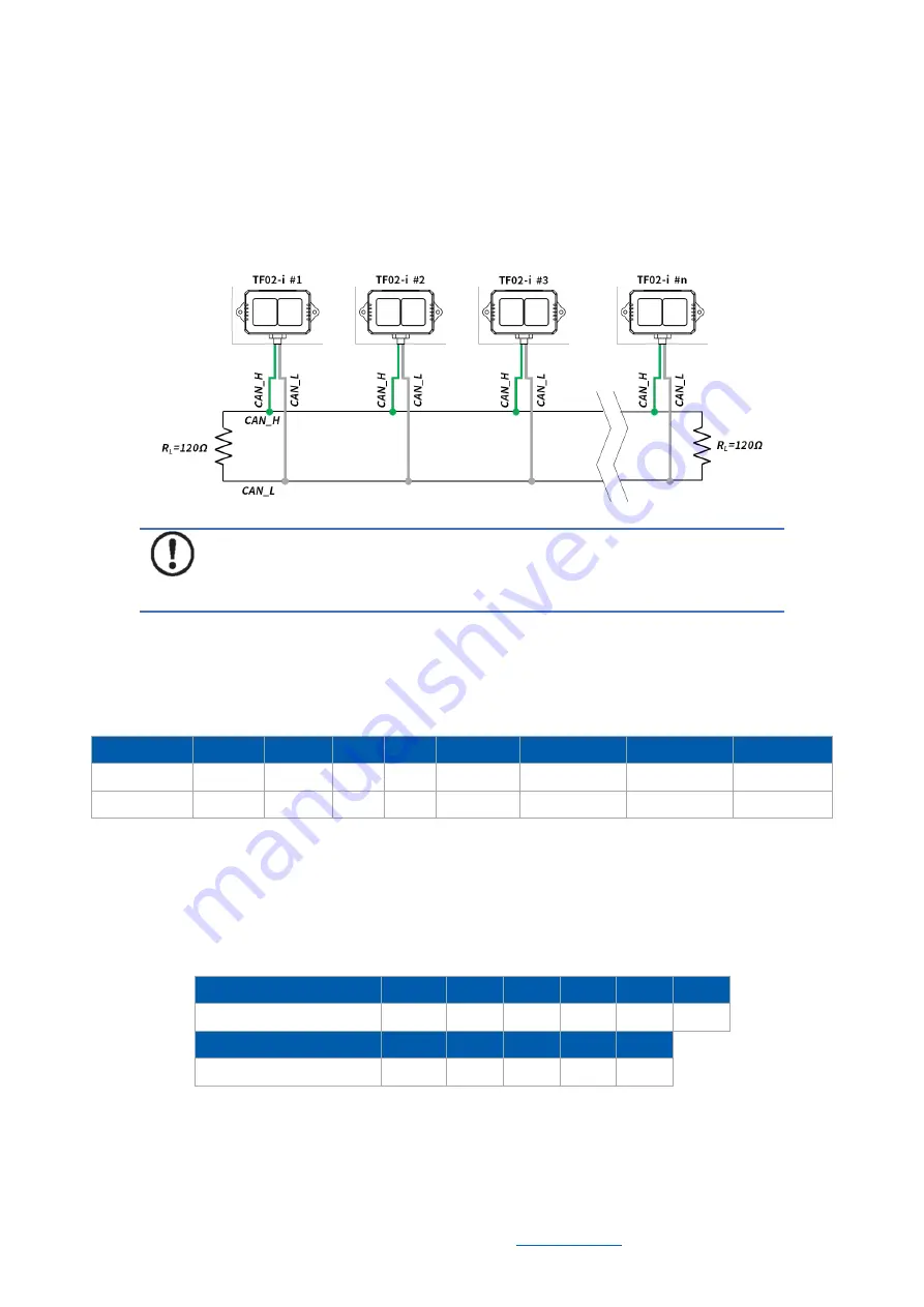
The CAN bus network is mainly hung in CAN_H and CAN_L, and each node performs
serial differential transmission of signals through two lines. In order to avoid signal
reflection and
interference, it is recommended to connect 120Ω end point resistors at
both ends of the bus, as shown in Figure 3-1.
Figure 3-1 CAN bus network of TF02-i
Note
It is recommended to contact Benewake to communicate the details of use
to complete networking requirements.
3.2.4
Parameter Configuration of CAN Communication
The configuration command format of CAN communication is shown as below.
Table 3-11 The configuration command format
Byte
0
1
2
3
4
5-8
9-12
13
Description Header Length
ID
Type Baudrate
Recv_id
Trans_id
Check_sum
Default
0x5A
0x0E
0x51
0
0x08
0x00000003 0x00000003
SU
Type: 0(Standard Frame), 1(Extended Frame);
Recv_id: TF02-i receiving ID, Little Endian;
Send_id: TF02-i transmitting ID, Little Endian.
Baudrate: The code of baud rate, default 250kbps, corresponding to 0x08. The relation
between baud rate(unit: kbps) and Byte4 is shown as below:
Table 3-12 The byte4 value corresponds to the baud rate
Byte4 value
0
1
2
3
5
6
Baud rate (unit: kbps)
1000
900
800
666
500
400
Byte4 value
8
10
11
14
16
Baud rate (unit: kbps)
250
200
160
125
100
Example of configuration:
Example1: Standard frame, Baud rate 500kbps, receiving ID=0x00000010, transmitting
ID=0x00000020
Command: 5A 0E 51 00 05 10 00 00 00 20 00 00 00 EE
Summary of Contents for TF02-i
Page 1: ...TF02 i User Manual...


