background image

TABLE OF CONTENTS


1.    INTRODUCTION 

2.    ANTIFOULING SYSTEM 

3.1.


WARRANTY/REGISTRATION


PROCEDURES 

3.1.1.


W

ARRANTY 

P

ROCEDURE


3.1.2.


R

EGISTRATION 

P

ROCEDURE


4


3.1.3.


W

ARRANTY 

T

RANSFER


3.2.


HULL


IDENTIFICATION


NUMBERS 

4.    DEALER'S RESPONSIBILITIES 

5.    OWNER'S/OPERATOR'S RESPONSIBILITIES 

5.1.


STATE


REGISTRATION


OR


FEDERAL


DOCUMENTATION 

5.2.


SAFETY


AND


MAINTENANCE 

5.3.


MANDATORY


COAST


GUARD


SAFETY


EQUIPMENT 

5.4.


RECOMMENDED


SAFETY


EQUIPMENT 

5.5.


SAFETY


COURSES 

5.6.


ANCHORING 

5.7.


ADDITIONAL


SAFETY


EQUIPMENT 

5.8.


MEDICAL


KIT 

5.9.


TOOL


KIT 

5.10.


SPARE


PARTS 

6.    SAFE OPERATION AND WARNING LABELS 

10 

6.1.


FUEL


WARNING


LABEL 

10 

6.2.


SHORE-POWER


LABEL 

10 

6.3.


PROPANE


LABELS 

11 

6.4.


SWIM


LADDER


WARNING


LABEL 

13 

6.5.


HIGH


VOLTAGE


WARNING


LABEL 

13 

6.6.


TRANSOM


DOOR


WARNING


LABEL 

14 

6.7.


STANDARD


BATTERY


SWITCH


LABEL 

14 

6.8.


OPTIONAL


BATTERY


SWITCH


LABEL 

14 

6.9.


SLING


LOCATION


ARROWS


LABEL 

15 

7.    FEDERAL/STATE REGULATIONS 

16 

Summary of Contents for Oceanis 321

Page 1: ...CE 6 5 3 MANDATORY COAST GUARD SAFETY EQUIPMENT 6 5 4 RECOMMENDED SAFETY EQUIPMENT 7 5 5 SAFETY COURSES 7 5 6 ANCHORING 8 5 7 ADDITIONAL SAFETY EQUIPMENT 8 5 8 MEDICAL KIT 8 5 9 TOOL KIT 9 5 10 SPARE PARTS 9 6 SAFE OPERATION AND WARNING LABELS 10 6 1 FUEL WARNING LABEL 10 6 2 SHORE POWER LABEL 10 6 3 PROPANE LABELS 11 6 4 SWIM LADDER WARNING LABEL 13 6 5 HIGH VOLTAGE WARNING LABEL 13 6 6 TRANSOM D...

Page 2: ... 10 3 1 HULL INSPECTION 22 10 3 2 ELECTRICAL INSPECTION 22 10 3 3 MACHINERY INSPECTION 22 10 3 4 RIGGING AND SAILS 23 10 3 5 FRESH WATER SYSTEM 23 10 3 6 HEAD SYSTEM 24 10 3 7 GALLEY 24 10 3 8 BILGE 24 11 MAINTENANCE OF YOUR BOAT 25 11 1 ANTI FOULING 25 11 2 GEL COAT 25 11 3 MINOR GEL COAT REPAIRS 26 11 4 THE DECK AND DECK FITTINGS 26 11 5 THE RUDDER 27 11 6 INTERIOR WOOD 27 11 7 ELECTRICAL SYSTEM...

Page 3: ... 13 2 5 CUTLASS BEARING 40 13 2 6 STUFFING BOX 40 13 2 7 DIESEL OPERATION 40 13 2 8 BEFORE STARTING THE ENGINE 40 13 2 9 STARTING THE ENGINE 41 13 2 10 STOPPING THE ENGINE 41 13 3 FUELING 43 13 3 1 BEFORE FUELING 43 13 3 2 FUELING 43 13 3 3 AFTER FUELING 43 13 3 4 FUEL SANITATION 44 13 3 5 BACTERIAL CONTAMINATION 44 13 3 6 FUEL ADDITIVES 44 13 3 7 FUEL SYSTEM HULLS 1 TO 64 45 13 3 8 FUEL SYSTEM HU...

Page 4: ...3 13 12 5 DECK ELECTRIC CIRCUIT 74 13 12 6 BATTERIES 75 13 12 7 12V CHARGING SYSTEM 75 13 12 8 REFRIGERATION 78 13 12 9 WINDLASS OPERATION 79 13 13 110V SHORE POWER SYSTEM 80 13 13 1 110V LAYOUT 80 13 13 2 110 VOLT SYSTEM 81 13 13 3 OPTIONAL 2ND BATTERY WIRING 83 13 13 4 CONDUIT ROUTING IN THE HULL LINER 84 13 13 5 OPTION CONDUIT ROUTING IN THE HULL LINER 85 13 13 6 SPEED AND DEPTH TRANSDUCER LOCA...

Page 5: ...RIGGING SPECIFICATIONS 106 13 15 15 RUNNING RIGGING SPECIFICATIONS 108 13 15 16 LIFELINE SPECIFICATIONS 111 13 16 SAILS 112 13 16 1 ROLLER FURLING MAINSAIL 112 13 16 2 CLASSIC MAINSAIL 113 13 16 3 ROLLER FURLING GENOA 116 APPENDIX I THRU HULL VALVE LOCATIONS ...

Page 6: ...me of printing and may be changed at any time or may have been changed on your boat While we have tried to describe the major points of your boat within this book we cannot cover every detail Please call your dealer or feel free to call us if any question should arise If you are a seasoned sailor much of the manual may be old news but if this is your first boat we hope this will prove useful Shoul...

Page 7: ...ct assures that the mechanical properties of your hull remain solid and it s life span greatly improved All materials used in the construction of your Beneteau are of the highest quality Sampling of materials and operational standards are constantly monitored so that the structural design matches the engineered standard Beneteau USA takes great care in the manufacturing of fiberglass parts as well...

Page 8: ...e recommendations as described in the owner s manual or non compliance with the normal rules of boat maintenance 11 failure to take reasonable measures necessary to protect the boat 12 any damage or deterioration to the boat resulting from participation in a competitive sporting event In addition if 1 any structural damage to the boat is suffered as a result of any cause other than a defect in mat...

Page 9: ...au Upon receipt of your completed and signed warranty form we will forward a new owners package directly to you Subsequent owners of Beneteaus are invited to become a member of Club Beneteau as well We will automatically enroll these boat owners upon receipt of their warranty transfer cards In the regulations event that you change your address please fill out and mail in the change of address card...

Page 10: ...ESPONSIBILITIES Your Beneteau Dealer is part of a worldwide distribution network with dealers in 28 countries As a Beneteau Dealer he has certain obligations to you as our customer and to Beneteau as our representative A Dealer s responsibility does not end with the sale of your boat Your Dealer is responsible for the following Deliver your new Beneteau to you complete as ordered in your purchase ...

Page 11: ...working order that you are aware of the weather conditions and someone ashore is familiar with your destination or sailing activities 5 3 MANDATORY COAST GUARD SAFETY EQUIPMENT Many safety items are required for compliance with the U S Coast Guard regulations Note that these regulations are subject to change It is the owner s responsibility to be aware of current regulations as outlined in the Fed...

Page 12: ...e of thumb to follow dictates that your bow stern and spring line be equal to the length of the boat Life jackets anchor anchor chain and line throwing line flares soft wooden plugs for thru hulls life ring fire extinguisher and foghorn Electronics Depth Sounder Log Speedometer and VHF Radio 5 5 SAFETY COURSES It is recommended that owners and operators gain knowledge and experience in boat safety...

Page 13: ...propriate chafing gear Carefull and regular inspection of moored boats on a regular basis is necessary to ensure the boat s safety 5 7 ADDITIONAL SAFETY EQUIPMENT A number of additional safety items are worthy of your consideration These range from safety harnesses to emergency beacons life rafts and survival suits Their use depends upon the intended use of the yacht We suggest you investigate the...

Page 14: ... spare blades 5 10 SPARE PARTS A basic kit should consist of the following Standing and Running Rigging Turnbuckles monel seizing wire clevis and cotter pins blocks extra line rigging tape duct tape Fasteners Assortment of stainless steel screws nuts bolts and washers Hose clamps Electrical Electrical tape wire crimps on lugs spare navigation light bulbs Lubricating supplies WD 40 and silicone gre...

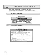
Page 15: ...Do not venture out in weather or sea conditions beyond the skill or experience of the operator There are Warning and Caution statements affixed to your Beneteau These are detailed below with location 6 1 FUEL WARNING LABEL Affixed to the fuel tank Beneteau Part 00001027 6 2 SHORE POWER LABEL At the 110V distribution panel Beneteau Part 00001028 ...

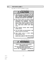
Page 16: ...03 02 07 11 9 08 AM REV 04 6 3 PROPANE LABELS At the propane stove affixed to the bulkhead in the galley Beneteau Part 00001021 Beneteau Part 00001026 ...

Page 17: ...03 02 07 12 9 08 AM REV 04 In the propane locker affixed under the propane locker lid Beneteau Part 00001024 On or next to the LP Gas Line Beneteau Part 00001030 ...

Page 18: ...03 02 07 13 9 08 AM REV 04 6 4 SWIM LADDER WARNING LABEL Located on the transom Beneteau Part 00001022 6 5 HIGH VOLTAGE WARNING LABEL Located beside the 110v electric panel Beneteau Part 00001034 ...

Page 19: ...Located on or next to the helmsman s seat Beneteau Part 00001031 6 7 STANDARD BATTERY SWITCH LABEL Located at the standard battery switches Beneteau Part 00001032 6 8 OPTIONAL BATTERY SWITCH LABEL Located at the optional battery switches Beneteau Part 00001023 ...

Page 20: ...u Part 00001033 6 10 ANTI FREEZE CAUTION TAG Tied to the breaker for the water Beneteau Part 00001038 CAUTION BOAT SHIPPED FROM FACTORY WITH ANTIFREEZE IN WATER SYSTEM CONSUMPTION OF ANTIFREEZE MAY CAUSE ILLNESS SYSTEM MUST BE THOROUGHLY FLUSHED SEVERAL TIMES TO REMOVE ANTIFREEZE BEFORE USE Beneteau 00001038 ...

Page 21: ...03 02 07 16 9 08 AM Rev 05 7 FEDERAL STATE REGULATIONS 7 1 DISCHARGE OF OIL Located under the sail locker lid Beneteau Part 00001007 ...

Page 22: ...eneteau Part 00001025 7 3 MARINE SANITATION Your Beneteau is equipped with an USCG approved marine head and holding tank By law you must use a holding tank in all U S waters Check with local authorities for regional laws governing your area before selecting the overboard discharge option ...

Page 23: ...the U S Coast Guard Boating Accident form For further information on where to obtain more forms please call the U S Coast Guard Boating Safety Hotline at 800 368 5647 NATIONAL VESSEL DOCUMENTATION CENTER 2039 STONEWALL JACKSON DR FALLING WATERS WV 25419 TOLL FREE 1 800 799 8362 PHONE 304 271 2400 FAX 304 271 2405 CREDIT CARD FAX 304 271 2415 ...

Page 24: ...v 05 9 RENDERING ASSISTANCE United States Code Title 46 The owner or operator of a vessel is required by law to render assistance to any individual or vessel in distress so long as his vessel is not endangered in the process ...

Page 25: ...do not attempt to provide step by step instructions Details of your yachts systems are available in section 13 of this manual and other manufacturers instructions that are provided with the yacht The factory installed equipment and items of responsibility that require attention by owner during commissioning are included in the list with the items marked with an asterisk the owner installed equipme...

Page 26: ...efore Stepping Mast WARNING MOVE YOUR BOAT TO A POSITION THAT IS CLEAR OF OVERHEAD WIRES OR OBSTRUCTIONS ELECTROCUTION MAY RESULT FROM CONTACT WITH ANY OVERHEAD WIRES Check the following items Shrouds stays spreaders installed and properly secured to mast Check standing rigging for kinks or defects Masthead lights spreader lights and mast mounted instrument units operational VHF antenna installed ...

Page 27: ...nel with the battery switch in the 1 2 and ALL positions 2 Make an operational check of all DC circuits connected to the electrical panel 3 Connect the shore power cable follow shore power operation instructions in section 13 check the polarity indicator close the main breaker and make an operational check of the following items if installed Battery Charger 110 volt outlets Be sure the heater has ...

Page 28: ...rd and reverse Check Throttle and shift controls Engine operation Alternator output Water temperature See engine owner s manual for operating temperature range Oil pressure See engine manual Check the fuel system for leakage Re check the propshaft seal for proper adjustment Adjust if necessary See propshaft seal manufactures instructions Install and check the operation of the emergency tiller 10 3...

Page 29: ...alve and discharge plumbing 10 3 7 Galley Check the following 1 Check all propane pipes hose fittings for leaks before lighting the stove DO NOT TEST FOR LEAKS WITH AN OPEN FLAME WIPE EACH JOINT WITH A SOAPY SOLUTION AND LOOK FOR BUBBLES 2 Galley stove operational 3 Galley sink drains correctly 4 Ice box drains correctly 5 Check all water hoses valves connectors and thru hulls for leaks 10 3 8 Bil...

Page 30: ...t for all FRP boats 11 1 GEL COAT The gel coat is vulnerable to any dents and scratches it may get during maneuvering in harbor and on a mooring The best way to avoid them is to undertake maneuvering calmly after thinking out all the relevant factors such as speed current wind and the layout of the harbor Always have one of the crew ready to put out a fender at the right place When bringing in the...

Page 31: ...ned out completely once a year Follow the manufacturer s instructions carefully When dismantling deck fittings have a bowl close at hand for putting the parts in and circle the area with a rolled dishcloth or the like so that any screws or springs you drop do not roll overboard Use the lubricant recommended by the manufacturer before reassembling Warning Incorrect reassembly can cause accidents No...

Page 32: ... suitable charger onboard so you can recharge your batteries at dockside without having to turn on the engine If you have an inboard engine check the condition and tension of the alternator drive belt From time to time spray a little WD 40 or something similar on all the connections to the control panel terminal boxes and lamp sockets Make sure that cable grommets are watertight smear them with Va...

Page 33: ...ve the boat unattended for several months disconnect the water lines purge them and rinse them thoroughly with vinegar and water so that they do not form foul smelling deposits Important If the electric pump continues running when all the taps are closed switch off the power supply at once and check the water system to find and overcome the leak that is causing this Check the thru hulls seacocks c...

Page 34: ... the engine compartment should be kept scrupulously clean check for any unusual oil or fuel leaks Inspect all the electrical connections frequently Drain the bowl of the fuel water separator at regular intervals to lessen the chance of water damage to your engine s fuel system Keep fuel tanks filled Inspect the engine mounts and coupling for loose bolts regularly Check the alternator belt for the ...

Page 35: ...il repair kit on board and a book showing how to carry out minor work yourself until you can get the job done by a professional sail maker Keep a special eye on points where the sails can chafe on the rigging or fittings turnbuckles lifelines shrouds spreaders etc Salt water and sunshine take their toll on sails Whenever possible rinse the sails in fresh water and leave them stretched out preferab...

Page 36: ...good boatyard is seasoned in hauling and maneuvering boats on land you may verify this by checking to see that the weight of the hull is resting firmly on the bottom of the keel and that even contact exists along the bottom of keel Jack stands or cradle uprights are meant to balance the boat and not to support its weight 12 2 BOTTOM Clean the yacht s bottom of any growth as soon as the boat is hau...

Page 37: ...lution placed into the supply tanks 6 New boats delivered have their freshwater systems filled with antifreeze as described above and are protected to 30 degrees F 12 6 HEAD Several days before completing haul out procedures fresh water should be allowed to stand in the head unit to dissolve any salt accumulation in the hoses and pump Remove all water from the head Special lubricants for the pump ...

Page 38: ... cable ends thoroughly of any corrosion with a baking soda and water solution and apply a light protective layer of petroleum jelly Batteries should be fully charged before storage and the fluid level maintained Store batteries in a warm dry place Do not store batteries directly on a stone or cement floor 12 10 SEACOCKS Open and drain all seacocks after boat is hauled Open all seacocks for winter ...

Page 39: ...een the winter cover and the boat is required to avoid build up of humidity CAUTION DO NOT USE BLACK POLYETHYLENE AND DO NOT SHRINK WRAP THE BOAT BY TAPING TO THE HULL ALWAYS ASSURE GOOD VENTILATION 12 16 SAILS Remove the sails clean following the sail makers recommendations and store in a clean dry space 12 17 MAST The aluminum mast requires a minimum of care and maintenance At the end of each se...

Page 40: ...PLIER INFORMATION LIST The following page lists our key suppliers in the United States If you need information from a supplier not listed you may contact Beneteau s Customer Service Department in Marion South Carolina at 1 843 423 6459 ...

Page 41: ...m Yourieff Sails 50 Broad Street Milford CT 06460 203 874 6984 203 877 7014 www paw com sail neilpryde Perkins Hot Line Perkins Engines 888 737 5364 Perko Lights P O Box 6400 D Miami FL 33164 305 621 7525 305 620 9978 Profurl Mark Reuther Profurl 401 N E 8th Street Ft Lauderdale FL 33304 800 272 9511 305 763 8790 104200 666 Compuserve Com PYI Whitlock Steering Max Prop PSS Shaft Seal PO Box 536 Ed...

Page 42: ...h 16 Stern Rail 28 Opening Porthole 5 Solid Vang 17 Deck Fill Fuel 29 Spring Line Fairlead 6 Deck Organizer 18 Stern Light 30 Genoa Track 7 Roof Handrail 19 Swim Ladder 31 Deck Porthole 8 Maneuvering Winch 20 Removable Helm Seat 32 Shroud Chainplate 9 Mainsheet Adjuster 21 Swim Platform Porthole 33 Hull Porthole 10 Sliding Hatch 22 Roller Fairlead 34 Deck Fill Fresh Water 11 Wood Entrance Door Wit...

Page 43: ... and maintenance procedures are provided in the engine manual supplied with your boat 13 2 2 Engine Installation 1 Engine Room Vent Hoses 10 Engine Battery 2 Fuel Tank 11 Raw Water Intake Thru Hull 3 Fuel Filter 12 Raw Water Filter 4 Stuffing Box 13 House Battery 5 Fuel Shut Off Valve 14 Shaft Coupler 6 Exhaust Hose 15 Engine Panel 7 Stuffing Box 16 Throttle Shift Lever 8 Water Muffler 17 Battery ...

Page 44: ...P G HOURMETER _ _ _ _ _ _ FUEL GAUGE OC PERKINS WIRE SCHEMATIC 3 PME01 P L G 1 2 3 4 5 6 3 START KEY SWITCH 4 TACHOMETER 5 COOLANT TEMPERATURE GAUGE 6 1 OIL PRESSURE LIGHT 2 CHARGE LIGHT WHITE RED BROWN BLACK BLACK BROWN BROWN YELLOW BROWN GREEN BLUE WHITE BROWN PERKINS BLACK WTE BRN BRN Y W W W W W B B W RED BRN GR BU BK BRN R GAUGES FUSE HOLDER 8 A ENGINE HOUSE FF01 FF01 TO ELECTRICAL PANEL _ _ ...

Page 45: ...ORIZED BY BENETEAU B ENETEAU INC P O Drawer 1218 Marion SC 29571 803 423 4201 Dimensions i n a N A N A OIL PRESS SW TACHOMETER C W TEMP FROM FUEL TANK FUEL GAUGE P L G CIRC WATER TEMP LAMP L O PRESSURE LAMP CHARGE LAMP BLU WH OR BU RED MCE01 MCE01 PUSH BUTTON SWITCH KEY SWITCH DWG No Part No _ _ _ _ _ _ STARTER ALTERNATOR FUSE WIRE SCHEMATIC ENGINE YANMAR 55 AMPS FA FA TO ELECTRICAL PANEL _ _ _ _ ...

Page 46: ...id switch 13 2 8 Before Starting the Engine 1 Open the raw water intake thru hull valve 2 Check to be sure the fuel shut off valve is open 3 Check the coolant level if the engine is fitted with a closed heat exchanger cooling system 4 Check the oil in the sump and gearbox this should be repeated after a few hours running 5 Check the tension of the alternator drive belt 6 Move the lever to neutral ...

Page 47: ...rse or vice versa the lever should be held in the neutral position for a moment before proceeding Shifting should be performed with RPM reduced to idle Keep a regular watch to make sure that the coolant water is circulating properly 13 2 10 Stopping the Engine To stop the engine 1 Place throttle transmission lever in the idle neutral position 2 Let engine idle for one 1 minute to allow it to cool ...

Page 48: ... of fuel not consumed during the factory engine tests may remain in the tanks Gauge markings 1 4 1 2 3 4 F Note number of gallons per mark X X X X Always sail with your tanks as full as possible both to avoid any contamination of the diesel oil with water due to condensation in the tank and to prevent the injector pump running dry and needing repriming 13 3 3 After Fueling Replace cover clean up a...

Page 49: ...most inopportune time Keeping water out of the fuel will of course prevent the problem entirely and while every effort should be made towards this such as obtaining fuel from reputable dealers it must be remembered that a certain amount of due to normal condensation in the tank is to be expected 13 3 6 Fuel Additives Fuel additives or conditioners provide means of combating this problem These addi...

Page 50: ...423 4201 Dimensions in Tol NONE NONE N A DWG No SYSTEM N A PLG CMC01 S1 Loctite 572 sealant 006474 DECK FILL Feed to Fuel shut off ca ble SYSTEM FUEL O321 HULL 1 TO 1 9 28 94 O321MC01 09070010 010789 13070032 04091015 Vent 005751 FUEL TANK ROTOMOLDED 002963 927700 025774 878800 029350 005158 13070010 021151 026066 021151 13070010 04091020 04091020 239300 206900 S1 S1 S1 S1 13070012 04091040 Return...

Page 51: ...74 13070032 04091015 03010007 S1 SUPPLIED WITH THE TANK 04091020 HOSE 5 16 13070010 CLAMP FUEL TANK ROTOMOLDED 09060321 O321MC0 CMC01 FEED LINE 04063507 HOSE BARB TANK 4 4 Fuel shut off cable 09070010 23 S1 S1 02115 9300 04091040 VENT 5 8 HOSE CLAMP 13070012 VENT 00575 0 FILTER S1 04063507 HOSE BARB 0 HOSE BARB 026066 VALVE 09084511 FUEL GAUGE 240 33 OHMS CMCE01 DECK FILL HOSE FUEL 1 1 2 HOSE CLAM...

Page 52: ...s approximately 90 degrees of travel and prevents rudder over travel which could damage the cable and chain assemble The type of pedestal steering system installed is a Whitlock 400 13 4 2 Wheel steering installation 1 Rudder 2 G R P Epoxy Pipe 3 Equilibrium ring 4 SS Ring PYD 5 Nylon Shoulder Bearing 6 SS Washer 7 Bored Quadrant 8 Emergency Tiller 9 Pin D12x150 2 Split Pins 10 Steering Wheel Supp...

Page 53: ...3 2 2007 9 08 AM Oceanis 321 Rev 00 50 ...

Page 54: ...entially tremendous load of a rudder turning freely while backing INSPECT the rudder stops on a regular basis to ensure they limit rudder travel to the correct amount failure to limit rudder play may result in steering failure CAUTION ALLOWING THE RUDDER AND WHEEL TO SPIN OUT OF CONTROL WHEN BACKING MAY CAUSE SERIOUS DAMAGE TO THE STEERING SYSTEM POSSIBLY RESULTING IN A DANGEROUS LOSS OF STEERING ...

Page 55: ... bleed off any trapped air in the lines until the water runs clear with no sputtering 5 Close all taps and the pump will turn off when it reaches operating pressure If the pump continues to cycle check all fittings for leaks Never top up with water and diesel at the same time if the filling points are close to each other to avoid the risk of contaminating one liquid with the other Similarly avoid ...

Page 56: ...ump House Under Stbd Midship Settee 7 Head Sink Shower 2 Fwd Water Tank 8 Head Supply Lines 3 Fwd Water Tank Supply Line 9 Transom Shower Supply Line option 4 Hot Water Heater 10 Transom Shower Valve option 5 Galley Sink 11 Transom Shower option 6 Galley Sink Supply Lines ...

Page 57: ...EI15 P S5 S5 028701 268247 532250 006731 WATER TANK TOP PART No S0 SEALANT NO SEALANT No CB BOLT FASTENER TYPE S1 3M 5200 S2 LOCTITE 577 S3 LOCTITE RED S4 3M 5230 S5 CLEAR NEUTRAL SILICONE MOBAY BAYSILONE 400 14025200 642450 14017262 14023230 14022210 CK BOLT SCREW COMBINATION CS SCREW S1 S1 S0 S5 231400 019111 010788 13070024 13070024 04090094 04090095 2 04090095 04090094 13070024 13070024 S2 S0 ...

Page 58: ...77 S3 LOCTITE RED S5 CLEAR NEUTRAL SILICONE MOBAY BAYSILONE 400 14025200 642450 14017262 14022210 NO SEALANT No CB BOLT FASTENER TYPE CK BOLT SCREW COMBINATION CS SCREW DECAL FRESH WATER PUMP 1 05090150 S0 S0 DECAL FRESH WATER STRAINER 04094004 236012 021285 021285 236012 236012 021285 021285 236012 SUPPLY I0 236012 021285 021285 236012 743600 236012 021285 021285 236012 743600 TOILET SUPPLY STBD ...

Page 59: ...Y SUPPLY AND DRAIN S0 S1 S2 S2 S0 S0 S0 S0 S0 S0 S0 S0 CHAIN PLUG SCREW STRAINER WASHER WASHER OUTLET WHEN USING 372200 DOUBLE SINK USE ONLY BOTH WASHERS THE OUTLET THE SCREW FROM 021391 COMPLETE OUTLET NOTE 372200 022627 022626 13070012 13070012 021389 13070012 13070012 342700 021391 PART OF PART OF 021391 026068 824700 05 23 94 05 23 94 O321 3210EIGP O3210CEI07 P No CB BOLT FASTENER TYPE CK BOLT...

Page 60: ...200 S2 LOCTITE 577 S3 LOCTITE RED S5 CLEAR NEUTRAL SILICONE MOBAY BAYSILONE 400 14025200 642450 14017262 14022210 NO SEALANT No CB BOLT FASTENER TYPE CK BOLT SCREW COMBINATION CS SCREW WATER EI0 EI0 S0 S2 S0 S1 S2 S2 05 12 94 05 12 94 236012 02128 02128 236012 236012 02128 02128 236012 13070012 13070012 025909 025909 13070012 13070012 342700 824700 S0 S0 535300 021141 021145 021145 021141 535300 S...

Page 61: ...3M 5200 S2 LOCTITE 577 S3 LOCTITE RED S5 CLEAR NEUTRAL SILICONE MOBAY BAYSILONE 400 14025200 642450 14017262 14022210 NO SEALANT No CB BOLT FASTENER TYPE CK BOLT SCREW COMBINATION CS SCREW AFT TOILET EI S2 S0 S0 S0 S0 738600 535300 021141 021145 236012 021286 021286 236012 743600 PRESSURE RELIEF VALVE OVERFLOW TO BILGE S2 S2 S0 535300 021141 021145 236012 021286 S0 S0 S0 236012 021285 021285 23601...

Page 62: ...i n Date NONE Tol NONE BADB PROTOTYPE 0 DWG No HOT WATER HEATER PART No S0 SEALANT S1 3M 5200 S2 LOCTITE 577 S3 LOCTITE RED S5 CLEAR NEUTRAL SILICONE MOBAY BAYSILONE 400 14025200 642450 14017262 14022210 NO SEALANT No CB BOLT FASTENER TYPE CK BOLT SCREW COMBINATION CS SCREW ENGINE WATER SUPP RET WATER TO ENGINE S0 S0 13070008 13070008 04090040 04090040 13070008 13070008 04067100 13070008 13070008 ...

Page 63: ... 0 COCKPIT SHOWER DWG No PART No S0 SEALANT S1 3M 5200 S2 LOCTITE 577 S3 LOCTITE RED S5 CLEAR NEUTRAL SILICONE MOBAY BAYSILONE 400 14025200 642450 14017262 14022210 NO SEALANT No CB BOLT FASTENER TYPE CK BOLT SCREW COMBINATION CS SCREW S0 019083 019084 015880 3210EEAP O3210CEE01P O321 05 11 94 05 11 94 S0 S2 027475 236012 021285 021285 236012 B FRESH WATER SUPPLY EI03 236012 021285 021285 236012 A...

Page 64: ...ipe and closed when it is at right angles 13 6 2 Safety Maintenance Take special care to see that these valves are well maintained have a good seal and work smoothly Have a wooden tapered plug of correct diameter at hand so that they can be plugged on the outside if for instance a seized valve has to be dismantled or lubricated After hot water has been run through a pipe for the first time check t...

Page 65: ...P O3210CIT11 P LOOP HOSE AS HIGH AS POSSIBLE PART No S0 SEALANT S1 3M 5200 S2 LOCTITE 577 S3 LOCTITE RED S4 3M 5230 S5 CLEAR NEUTRAL SILICONE MOBAY BAYSILONE 400 14025200 642450 14017262 14023230 14022210 NO SEALANT No CB BOLT FASTENER TYPE CK BOLT SCREW COMBINATION CS SCREW S5 S0 S2 S2 S0 S2 S1 S2 S0 S0 S0 S0 S0 S0 S0 S2 S2 S1 623700 824700 026068 342700 13070012 13070012 025909 025909 13070012 1...

Page 66: ...elect the overboard discharge position on the Y valve by turning the lever in the opposite direction of the overboard discharge hose 4 Select Flush Bowl with the selection lever on top of the pump body and pump the handle until the bowl is flushed clean Return the selection lever to Dry Bowl and pump the handle until the bowl is dry The holding tanks capacity is approx 12 gallons limiting pump str...

Page 67: ...By View THIS DOCUMENT IS PROPRIETARY REPRODUCTION MUST BE AUTHORIZED BY BENETEAU B ENETEAU USA P O Drawer 1218 Marion SC 29571 803 423 4201 Part No PROTOTYPE 0 NONE Dimensions in __ ial Gen Tol NONE __ BADB PLUMBING SYSTEM DWG No MANUAL BILGE DRAINING S1 S S0 S1 PART No S0 SEALANT S1 3M 5200 S2 S3 14025200 NO SEALANT No CB BOLT FASTENER TYPE CK BOLT SCREW COMBINATION CS SCREW 14023230 3M 5230 1402...

Page 68: ...tarboard middle settee in the main saloon To drain the bilge or icebox select the correct position with the valve and turn on the pump The pump is controlled from a switch on the main 12V panel Be sure to clean the filter between the pump and sump carefully at regular intervals To clean the filter unscrew the body and wash out the filter screen WARNING BE CAREFUL NOT TO WASH THE O RING SEAL OUT OF...

Page 69: ...070012 13 070012 13070012 025909 05092000 128500 324600 REMOVE CHAIN FROM PLUG 129300 13070012 025909 025909 13070012 342700 13070012 13070012 825000 S2 S0 342700 13070012 025909 S2 S0 S S0 2 342 00 130700 130700 PART No S0 SEALANT S1 3M 5200 S2 LOCTITE 577 S3 LOCTITE RED S5 CLEAR NEUTRAL SILICONE MOBAY BAYSILONE 400 14025200 642450 14017262 14022210 NO SEALANT No CB BOLT FASTENER TYPE CK BOLT SCR...

Page 70: ...kpit is drained thru 2 tubes located at the outboard aft corners of the cockpit Make sure that these drain holes are not blocked When using the cockpit as a workshop plug drain holes with large cork bungs to avoid the loss of any nuts or bolts which you may accidentally drop ...

Page 71: ...BOLTS CAST INTO THE LEAD WITH 1 NUT WELDED ON THE END AND 1 MORE MIDWAY IN THE LEAD SS THREADED WELDED NUT THIS REPLACES THE GRID USED ON THE ORIGINAL DRAWING 2 LENGTH OF THREADED BOLTS CAST INTO THE LEAD MUST BE THE SAME AS ON THE ORIGINAL DRAWING 301 150 470 165 131 75x75x 466500 466500 64x64x 102x102x9 5 46650044 9 5 1 1 2 SS 1 1 4 SS 3 4 SS BACKING PLATE SS HOLE 46650043 SS 280x141x9 5 2 S USE...

Page 72: ...rt in a seaway The stove is supplied by a storage bottle located in a self draining locker in the cockpit The pressurized gas is fed thru a regulator at the bottle which reduces the pressure and feeds the propane gas to a 12V solenoid valve The solenoid is a remotely controlled valve which turns the flow of gas on and off from a switch located at the 12V distribution panel A pressure gauge is loca...

Page 73: ...2 S2 LABEL LABEL LABEL S0 S0 S0 S0 S4 500mm S0 S0 S0 S0 S4 1000mm LABEL LABEL LABEL 01 02 03 04 05 06 07 08 0 0 0 0 0 0 0 LPG PIG TAIL FOR REMOTE CONNECTION 24 1014140224 HEX NIP PLE 1 4 STREET TEE 1 4 GAUGE P RESSURE 300 PSI SINGLE STAGE L P REGULATOR BODY HEX NIP PLE 3 8 SOLENOI D LOW PRESSURE TYP 0 4 PSI ELBOW 3 8 MPT x 3 8 MALE FLARE 130077062 1 2 3 4 5 6 7 8 0 S0 No PART DESCRIPTION ________ ...

Page 74: ...n 4 Open the supply valves and test the system for leaks following the instructions on the locker warning label 5 Light the appliance in accordance with the stove manufactures procedures Generally each burner is lit by turning the burner control knob to the lighting position and then pushing the knob in A safety thermocouple will keep the valve open as long as the burner remains lit If the flame g...

Page 75: ...a a distribution panel This panel separates the current into separate circuits Each circuit is protected by an individual breaker switch which allows you to turn the individual circuits on or off as needed at the panel Each breaker switch has an individual amperage rating which it is designed to trip at in case it is overloaded 13 12 2 Panel Wiring Schematic ...

Page 76: ...nected together at the wiring block strip using a series of plugs from each that snap onto opposite sides of the wiring block strip Each of the boats positive 12V circuits connect to it s circuit breaker in the panel this way ie Wire 7 Deck Light connects across the wiring block to circuit breaker 7 on the panel The negative side of the circuits lead to a common ground ...

Page 77: ...ck strip These individual blocks can be connected to the blocks on either side of it to create a larger circuit as in the saloon lights Wires are inserted into the block by 1 Inserting a small screwdriver into the inside hole and pressing down 2 Insert the wire 3 Remove the screwdriver Remove wires by inserting the screwdriver and pulling out the wire ...

Page 78: ...3 2 2007 9 08 AM Oceanis 321 Rev 00 75 13 12 4 Lighting Layout ...

Page 79: ...enoid 30 Port Fwd Cabin Reading Light 31 Stbd Fwd Cabin Reading Light 32 Stbd Aft Cabin Ceiling Light 33 Stbd Aft Cabin Reading Light 34 Stbd Aft Cabin Reading Light 40 Port Salon Ceiling Light 41 Stbd Salon Ceiling Light 43 Galley Fluorescent Light 44 Chart Table Light 48 Aft Stbd Toilet Light 50 Galley Ceiling Light 98 Repeater Feed ...

Page 80: ...ne when the battery is cold and has not been recharged or used for several hours beforehand A reading of less than 11 5 V means that recharging is necessary WARNING NEVER OPERATE ISOLATING SWITCHES WHILE THE ENGINE IS RUNNING DOING SO COULD DAMAGE THE ALTERNATOR DIODES AND REGULATOR BEYOND REPAIR 13 12 7 12V Charging System The batteries must be recharged by one of the following systems ...

Page 81: ... ENGINE NEGATIVE ENGINE 12V PANEL B 13 12 7 2 Battery Charger A marine battery charger is wired into the 110V shore power system This charger converts the AC dock power to 12V DC and feeds it to the batteries WARNING DO NOT OPERATE THE CHARGER WHEN THE ENGINE IS RUNNING The battery charger is completely automatic refer to the charger s manual for complete details To charge the batteries using the ...

Page 82: ... SC 29571 803 423 4201 Dimensions in Tol NONE NONE N A DWG No SYSTEM N A PLG SENTRY 0 20 30 SENTRY BATTERY CHARGER 12V SYSTEM 110V SYSTEM BAT 2 BAT 1 NEG BAT L1 GRD N 15A 10A 15A 30A LINE NEUTRAL LINE HOT WATER HEATER BATT CHARG OUTLETS OUTLET TERM STRIP NEUTRAL BUS AC GND BUS HOT BUS AC GROUND MAGNETIC CIRCUIT BREAKERS 14AWG BK 10AWG WHITE 89 2230 2 110V SHORE POWER WHITE BLACK GREEN ENGINE HOUSE...

Page 83: ...3 2 2007 9 08 AM Oceanis 321 Rev 00 80 13 12 8 Refrigeration ...

Page 84: ...PSY DAMAGING THE WINDLASS THE BOAT OR CAUSE PERSONAL INJURY Set the anchor by engaging the engine in reverse briefly Do not set the anchor by pulling in with the windlass Always make the anchor rode fast on a cleat when the anchor is set Do not rely on the windlass brake to hold the boat WARNING THE MOTION OF THE BOAT AT ANCHOR CAN CAUSE LOADS ON THE ANCHOR RODE THAT MAY DAMAGE THE WINDLASS Always...

Page 85: ... outlets and appliances on your boat The shore power system is rated for a maximum of 30AMPS care must be taken to not overload the system WARNING DO NOT WIRE OPTIONAL AIR CONDITIONERS TO THE SHORE POWER SYSTEM INSTALL A SEPARATE SERVICE AND PANEL The 110V panel consists of breaker switches which protect and turn the individual circuits on and off The charger hot water heater and the 110V outlet c...

Page 86: ...ensions in Tol NONE NONE N A SYSTEM N A PLG 120 13 0 14 0 150 H C SENTRY 0 20 30 SENTRY L1 N G W B B G W G HOT WATER HEATER BATTERY CHARGER OUTLETS W 15A 10A 15A 30A LINE NEUTRAL LINE HOT WATER HEATER BATT CHARG OUTLETS OUTLET TERM STRIP NEUTRAL BUS AC GND BUS HOT BUS AC GROUND MAGNETIC CIRCUIT BREAKERS 14AWG BK 10AWG WHITE 89 2230 2 110V SHORE POWER WHITE BLACK GREEN G W B B W G B W G W B G S Y S...

Page 87: ...down the diesel engine 2 Switch all 110V breakers off 3 Switch the dock outlet breaker off 4 Plug the shore power cord into the boat and dock outlet 5 Switch the dock breaker on 6 Switch the panel breakers on as needed WARNING DO NOT OPERATE THE 110V WATER HEATER DRY ...

Page 88: ... O Drawer 1218 Marion SC 29571 803 423 4201 Dimensions i n a N A N A P L G CIRC WATER TEMP LAMP L O PRESSURE LAMP CHARGE LAMP BLU WH OR BU RED PUSH BUTTON SWITCH KEY SWITCH DWG No Part No 2 22 95 _ _ _ OPTION BATTERY COMMON OPTION 2d BATTERY OC 321 WIRING _ _ _ BATTERY CHARGER OIL PRESS SW TACHOMETER C W TEMP G FUEL GAUGE _ _ _ HOURMETER _ _ _ FROM FUEL TANK MCE01 MCE01 STARTER FUSE SWITCHES _ _ E...

Page 89: ...3 2 2007 9 08 AM Oceanis 321 Rev 00 86 13 13 4 Conduit Routing In The Hull Liner ...

Page 90: ...1 Rev 00 87 13 13 5 Option Conduit Routing In The Hull Liner 1 Depth sounder to electric panel 2 Water Heater to electric panel 3 Electric panel access behind the stove 4 Engine room to electric panel 5 Transom to electric panel ...

Page 91: ...3 2 2007 9 08 AM Oceanis 321 Rev 00 88 13 13 6 Speed and Depth Transducer Location ...

Page 92: ...05 OPENING PORT 03012508 PLASTIC 03012423 INCLUDED CURTAIN 0 OPENING PORT 03012508 PLASTIC 03012423 INCLUDED NONE COACHROOF 00 01 OPENING HATCH 03012020 GRP OF DECKLINER BLIND 006099 COCKPIT 01 OPENING PORT 03012508 PLASTIC 03012423 INCLUDED TRANSOM 01 OPENING PORT 03012508 PLASTIC 03012423 INCLUDED COACHROOF COAMING DECK DECK HULL HULL 05 02 COACHROOF 3 2 05 AFT CABIN TOILET FORWARD CABIN SALON C...

Page 93: ...n your Oceanis is discontinuous This arrangement saves weight aloft by eliminating extra shrouds The sails are attached to the mast boom and genoa furler The sails are shaped and controlled by the running rigging 1 Cap Shroud V1D2 2 Spreader Tip 3 Backstays 4 Babystay 5 Aft Lowers Shroud D1 6 Chainplate Turnbuckles 7 Masthead 8 Forestay 9 Spreaders 10 Roller Furling Drum Above Deck ...

Page 94: ...3 2 2007 9 08 AM Oceanis 321 Rev 00 91 13 15 2 Measurements ...

Page 95: ...r the mast in the boat by tightening the V1 s alternately until the masthead is centered athwart ships Attach a tape measure to the main halyard and measure to opposite points on the toerail to check the position 8 Commence tightening the V1 s with equal turns on each side until they become tight Be sure the D2 s do not come under any tension during this process 9 When the V1 s are tight start ten...

Page 96: ...XED MAINSHEET YSYTEM MAINSHEET SYSTEM WITH TRAVELLER CONTROL LINE DESCRIPTION MAST STEP BLOCK STD or OPT POS 01 JIB HALYARD PIVOTTING SCH561159 STANDARD 02 MAIN HALYARD PIVOTTING SCH561159 STANDARD 03 INHAUL SWIVELLING SCH561171 STANDARD 04 OUTHAUL SWIVELLING SCH561171 STANDARD 0 MAINSHEET LEWMAR 9 17 STANDARD 0 0 9217 SINGLE JIB HALYARD IS LED THRU MAST STEP BLOCK AND LED DIRECTLY TO HALYARD WINC...

Page 97: ...3 2 2007 9 08 AM Oceanis 321 Rev 00 94 13 15 5 Roller Furling Mast Drawing ...

Page 98: ...preader WHISKER POLE TOPPING LIFT SHEAVE BOX BABY STAY BACKING PLATE TEE BALL FOR 7 32 WIRE BF3 SPREADER BASE STEAMING LIGHT PERKO 1331 MOUNTING PLATE FOR STEAMING LIGHT CORE ELECTRICAL CABLE POLE TOPPING LIFT SHEAVE BOX SPINNAKER 2 WHISKER POLE TOPPING LIFT EXIT SLOT PLASTIC GENNEKER HALYARD PORT SHEAVE EXIT SLOT PLASTIC MAIN BOOM TOPPING LIFT PORT SHEAVE EXIT SLOT PLASTIC MAIN ROLLER FURLING DRU...

Page 99: ...nd to wrap more line onto the drum 3 Lower the main swivel hoist car to the gooseneck with the main halyard 4 Attach the mainsail headboard to the shackle on the bottom of the swivel car 5 Hoist the mainsail slowly feeding the luff tape into the extrusion luff groove 6 Attach the mainsail tack to the lower swivel shackle and tension the luff with a winch 7 Run the out haul line thru the block on t...

Page 100: ...T HAUL LINE CONTROLS THE SAIL SHAPE 3 Always furl and unfurl the main with the boat head up to wind 4 The main is unfurled by easing out the furling line while taking up on the mainsail out haul 5 The main is furled by taking in on the main inhaul line it is important to feed the out haul line as you furl the main 6 NOTE NEVER TAKE IN ONE LINE WITHOUT KEEPING A LITTLE TENSION ON THE OPPOSITE LINE ...

Page 101: ... MOST SHEAVE LINE COLOUR DIA LENGTH PORT MOST PORT INNER STBD INNER STBD MOST ISOMAT 0801 0 PROTOTYPE BOOM KIT F220 032 08 01 94 08 01 94 EMPTY EMPTY OUTHAUL FOR ROLLER FURLING MAST O321 1 EMPTY EMPTY EMPTY EMPTY EMPTY BLACK 3 8 14000 1 VANG MOVED 1150 INHAUL to BLOCK to 1000 10 15 94 0000 SOLID MECHANICAL VANG ATTACHMENT MAINSHEET MAINSHEET FOR INHAUL BLOCK NO JAMMERS OUTHAUL PIVOT BLOCK OUTHAUL ...

Page 102: ...rawer 1218 Marion SC 29571 803 423 4201 Part No Dimensions in Tol 0 PROTOTYPE Millimeters NONE NONE N A BADB DWG No 321 O321 08 08 94 08 08 94 LINE 2 LINE 1 LINE 2 RUNS THRU EYE ON LINE 1 STAINLESS STEEL RING 32mm ID LINE 3 LINE 4 STKPK STKPK LAZY JACK AND DOYLE STACK PACK LIGHT O321 LAZY JACK CLEAT FOR LINE 4 BALE USED AS FAIRLEAD FOR LAZY JACK LINE 4 BALE USED TO TIE OFF LAZY JACK LINE 3 LINE RE...

Page 103: ...YSYTEM MAINSHEET SYSTEM WITH TRAVELLER 9217 SINGLE JIB HALYARD IS LED THRU MAST STEP BLOCK AND LED DIRECTLY TO HALYARD WINCH FOR TENSIONNING AFTER TENSIONNING JIB HALYARD JAM OFF ON CLAMCLEAT AND STO ON BACK UP CLEAT VANG LINE CLEATED ON SOLID VANG VANG LINE CLEATED ON SOLID VANG Z Z CLASSIC MAST 2 SHACKLE OF VANG BRACKET 2 SHACKLE OF VANG BRACKET WE TAIL MAINSHEET VANG CONTROL LINE DESCRIPTION MA...

Page 104: ...R SPREADER deg 1 46 7 WHISKER POLE TOPPING LIFT EXIT SLOT PLASTIC PORT SHEAVE MAIN BOOM TOPPING LIFT HALYARD GENNEKER PORT MOST SHEAVE EXIT SLOT PLASTIC EXIT SLOT PLASTIC EXIT SLOT PLASTIC EXIT SLOT PLASTIC RACING VERTICAL CLAMCLEAT FOR JIB 1 HALYARD 2 19 STEAMING LIGHT PERKO 1331 MOUNTING PLATE FOR STEAMING LIGHT 2 CORE ELECTRICAL CABLE MAINSAIL FEEDER GATE VANG MAST BRACKET WITH SHACKLE FOR MAIN...

Page 105: ...GTH REEF 1 PORT MOST PORT INNER STBD INNER STBD MOST REEF 1 ISOMAT 3 8 3 8 0801 0 PROTOTYPE BOOM KIT CLASSIC F220 032 O321 08 01 94 08 01 94 WITH AUTO REEF REEF 2 EMPTY OUTHAUL RED GREEN BLACK 3 8 7000 16000 9000 17500 REEF 2 EMPTY OUTHAUL 2 3000 3000 1 VANG MOVED 1495 to 1150 10 15 94 0000 E 4150 3 1 OUTHAUL CLEATED ON JAMMER LAZY JACK CLEAT SOLID MECHANICAL VANG ATTACHMENT MAINSHEET MAINSHEET LA...

Page 106: ... BENETEAU B ENETEAU INC P O Drawer 1218 Marion SC 29571 803 423 4201 Part No Dimensions in Tol 0 PROTOTYPE Millimeters NONE NONE N A BADB 0000 SOLID VANG 080150 LOWER UPPER LINE COLOUR DIA LENGTH VANG 1 O CLAMCLEAT YELLOW 2 08 01 94 08 01 94 321 ISOVANG SOLID VANG 1 4 8300 SHOCKORD LINE WHITE 1 4 1300 KNOT BALL 0140 1600 1 VANG SHORTENED 2040 to 1600 HULL 7 ONWARDS 10 15 94 ...

Page 107: ...esign date By View THIS DOCUMENT IS PROPRIETARY REPRODUCTION MUST BE AUTHORIZED BY BENETEAU B ENETEAU USA P O Drawer 1218 Marion SC 29571 803 423 4201 Part No PROTOTYPE 0 NONE Dimensions in __ ial Gen Tol NONE __ BADB 0802 08 31 94 08 31 94 DWG NO 0135 PART OF KIT 08020135 O321 0000 BABYSTAY BABY 2 3 OPEN 7145 ...

Page 108: ... DOCUMENT IS PROPRIETARY REPRODUCTION MUST BE AUTHORIZED BY BENETEAU B ENETEAU USA P O Drawer 1218 Marion SC 29571 803 423 4201 Part No PROTOTYPE 0 NONE Dimensions in __ ial Gen Tol NONE __ BADB 0802 08 31 94 08 31 94 DWG NO 0135 PART OF KIT 08020135 O321 BACKSTAY BACK 2 3 OPEN 2 3 OPEN 00000 13720 ...

Page 109: ...w THIS DOCUMENT IS PROPRIETARY REPRODUCTION MUST BE AUTHORIZED BY BENETEAU B ENETEAU USA P O Drawer 1218 Marion SC 29571 803 423 4201 Part No PROTOTYPE 0 NONE Dimensions in __ ial Gen Tol NONE __ BADB 0802 08 31 94 08 31 94 DWG NO 0135 PART OF KIT 08020135 0000 O321 2 3 OPEN D1 LOWER SHROUD D1 7030 ...

Page 110: ...TEAU USA P O Drawer 1218 Marion SC 29571 803 423 4201 Part No PROTOTYPE 0 NONE Dimensions in __ ial Gen Tol NONE __ BADB 0802 08 31 94 08 31 94 DWG NO 0135FORE PART OF KIT 08020135 FORESTAY O321 2 3 OPEN 00000 00051 013285 FASTEN TURNBUCKLE EYE TO DOUBLE JAW TOGGLE AND ROLLER FURLING UNIT LINK PLATES FASTENER SUPPLIED WITH ROLLER FURLING UNIT LINK PLATES USING IMPORTANT ...

Page 111: ... THIS DOCUMENT IS PROPRIETARY REPRODUCTION MUST BE AUTHORIZED BY BENETEAU B ENETEAU USA P O Drawer 1218 Marion SC 29571 803 423 4201 Part No PROTOTYPE 0 NONE Dimensions in __ ial Gen Tol NONE __ BADB 0802 08 31 94 08 31 94 DWG NO 0135 PART OF KIT 08020135 00000 V1D2 CAP SHROUD O321 V1D2 2 3 OPEN 13065 ...

Page 112: ...3 2 2007 9 08 AM Oceanis 321 Rev 00 109 13 15 14 Standing Rigging Specifications ...

Page 113: ...3 2 2007 9 08 AM Oceanis 321 Rev 00 110 ...

Page 114: ...3 2 2007 9 08 AM Oceanis 321 Rev 00 111 ...

Page 115: ...3 2 2007 9 08 AM Oceanis 321 Rev 00 112 13 15 15 Running Rigging Specifications ...

Page 116: ...3 2 2007 9 08 AM Oceanis 321 Rev 00 113 ...

Page 117: ...3 2 2007 9 08 AM Oceanis 321 Rev 00 114 ...

Page 118: ...3 2 2007 9 08 AM Oceanis 321 Rev 00 115 ...

Page 119: ...3 2 2007 9 08 AM Oceanis 321 Rev 00 116 13 15 16 Lifeline Specifications ...

Page 120: ...8mm FOOT min tension 4090mm FOOT max tension E 4150mm ITEM TO DETAIL ITEM QUANTITY SIZE TYPE MAKE and PART NUMBER SAILCLOTH 245 g m HEAD 25mm webbing loop TACK 25mm webbing loop CLEW webbed on clew block Seasure 04 87 CLEW safety ring Inox pressed ring 211 LUFF bolt rope 7 luff tape 7 32 LEECH line cleat aluminium clamcleat CL241 UV COVER UV clew patch 245g m both sides INSIGNIA none TELL TALES 2 ...

Page 121: ...QUANTITY SIZE TYPE MAKE and PART NUMBER SAILCLOTH 345 g m HEAD aluminium headboard 5 1 4 x 1 8 Aquabatten B812 TACK 1 1 4 x 1 4 ss round ring webbed on cutback cut up TACK reef 1 1 1 4 x 1 4 ss round ring webbed on cutback 150mm cut up TACK reef 2 1 1 4 x 1 4 ss round ring webbed on cutback 150mm cut up CUNNINGHAM none CLEW 1 1 2 x 5 16 ss round ring webbed on CLEW reef 1 Inox pressed ring 212 sin...

Page 122: ...3 2 2007 9 08 AM Oceanis 321 Rev 00 119 Classic Mainsail FOOT LEECH LUFF ...

Page 123: ...ion 6096mm ITEM TO DETAIL ITEM QUANTITY SIZE TYPE MAKE and PART NUMBER SAILCLOTH 245 g m HEAD 25mm webbing loop TACK 25mm webbing loop CLEW Inox pressed ring 213 single webbing strap LUFF bolt rope 6 luff tape 3 16 LEECH line cleat aluminium Clamcleat CL241 UV COVER UV leech and foot 170g m starboard side only FOOT line cleat 2 grommets for lashing 3 grommets INSIGNIA none TELLTALES telltales at 2...

Page 124: ...08 AM Oceanis 321 Rev 00 121 APPENDIX THRU HULL VALVE LOCATIONS NOTE THRU HULL VALVES SHOULD BE CLOSED WHEN NOT IN USE PICTURE 1 MID SALON NOTE ONLY ONE OF THESE VALVES SHOULD BE OPEN DURING NORMAL PUMP OPERATION ...

Page 125: ...3 2 2007 9 08 AM Oceanis 321 Rev 00 122 PICTURE 2 UNDER GALLEY SINK PICTURE 3 UNDER AFT STBD BUNK ...

Page 126: ...3 2 2007 9 08 AM Oceanis 321 Rev 00 123 PICTURE 4 UNDER STBD HEAD SINK PICTURE 5 UNDER AFT SALON SETTEE ...

Page 127: ...3 2 2007 9 08 AM Oceanis 321 Rev 00 124 PICTURE 6 STBD HEAD CABINET ABOVE SINK ...

Reviews: