20
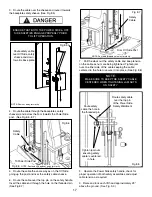
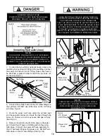
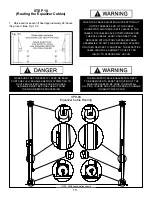
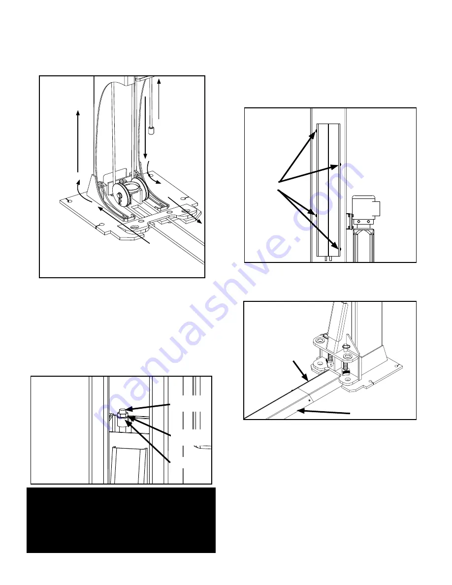
2. With the lift heads locked at 28” off the floor, uncoil the
equalizer cables and
route the threaded end of the equal-
izer cables towards the Base Plate sheave. Wrap the
cable around the base plate sheave and reinstall sheave.
(See Fig. 10.2)
3.
Route the threaded cable end to the opposite post’s
base plate sheave. Wrap the cable around the opposite
post’s Base Plate sheave and reinstall sheave.
(See Fig. 10.2)
4. Route threaded end upwards from Base Plate sheave
and insert the threaded end of the cable through the cable
holder on top of the lift head. Place M18 washer and M18
Nylock nut on threaded cable end. Tighten cable nuts until
cable is taut. Check that both cables have equal tension.
(See Fig 10.4)
STEP 11
(Installing power unit hose assembly
and Power Side safety cover)
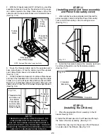
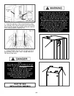
1. After safeties have been adjusted and checked for
proper operation, install and tighten Power Side safety
cover and Off Side safety cover mounting screws.
(See Fig. 11.1)
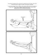
2. Install the floor plate between the columns as shown.
For Wide configuration use the floor plate extension.
(See Fig. 11.2)
STEP 12
(Installing the Lift Arms)
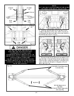
1. Place the appropriate lift arm assembly in the lift
heads. (See Fig. 12.5)
2. Install the lift head pins into the lift head and through
the holes in the arm assembly. (See Fig. 12.1)
3. Install the snap ring into the groove in the lift head pin
on under side of the lift head. (See Fig. 12.2)
Fig 10.2
From opposite
Base Plate sheave
NOTE: Post and lift head cut away for clarity
To opposite
Base Plate
sheave
To Top
Plate
sheave
To cable
holder
Threaded cable
end comes up
from Bottom
Plate sheave
and into cable
retainer on top
of the lift head.
Threaded
Cable End
Nylock
Nut
Fig. 10.4
Washer
Fig. 11.1
Screw
Floorplate
Floorplate
Extension
Fig. 11.2
NOTE:
THERE WILL BE INITIAL STRETCHING OF THE
CABLES AND/OR WITH INCREASED LOADS.
ADJUST THE CABLES AS OUTLINED ABOVE A
WEEK AFTER FIRST USE, THEN EVERY THREE TO
SIX MONTHS THEREAFTER DEPENDING ON USAGE
AND/OR TO COMPENSATE FOR STRETCH.

