


1
®
Bendix
®
TU-FLO
®
600 Air Compressor
SD-01-336
GENERAL
The function of the air compressor is to build up and maintain
the air pressure required to operate air powered devices in
air brake or air auxiliary systems.
DESCRIPTION
The Tu-Flo
®
600 compressor is a two cylinder reciprocating
single stage compressor with a rated displacement of 14.5
cfm at 1250 rpm.
The Tu-Flo
®
600 compressor is constructed with a crankcase,
block, and head assembly. The crankcase assemblies, in
particular, are essentially the same as corresponding Tu-Flo
®
500 compressors. The block assembly includes the air inlet
cavity, automatic inlet valves and unloader valves. Vertical
mounting pads for governor mounting are included at each
end of the block. The head assembly includes the discharge
valves with discharge ports either on the side or top of the
block.
All Tu-Flo
®
600 compressors are liquid cooled, both head
and block, by coolant from the engine cooling system.
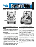
Various mounting and drive configurations are used as
required by different vehicle and engine designs. See Fig. 1.
All Tu-Flo
®
600 compressors receive oil under pressure from
the engine lubricating system for the lubrication of the
internal parts. Fig. 2 shows a cross section of a typical
Tu-Flo
®
600 compressor and the oil flow therein.
Oil is forced through the oil passage in the crankshaft to
each connecting rod journal. Oil is forced out at the journals
and is thrown by centrifugal force against the cylinder walls
and crankshaft main bearings, providing lubrication.
The wrist pins and wrist pin bushings are lubricated in two
ways depending on the type connecting rod used. Some
older compressors, and one current design use forged steel
rifle drilled rods, through which oil is forced to the wrist pin
bushings. Standard current design consists of a diecast
aluminum or forged steel rod with an “oil catch-funnel” at
the top of the rod and a short hole connecting to the wrist
pin bushing. See Fig. 3.
TU-FLO
®
600 AIR COMPRESSOR VERTICAL MOUNT
TU-FLO
®
600 AIR COMPRESSOR FLANGE MOUNT