2
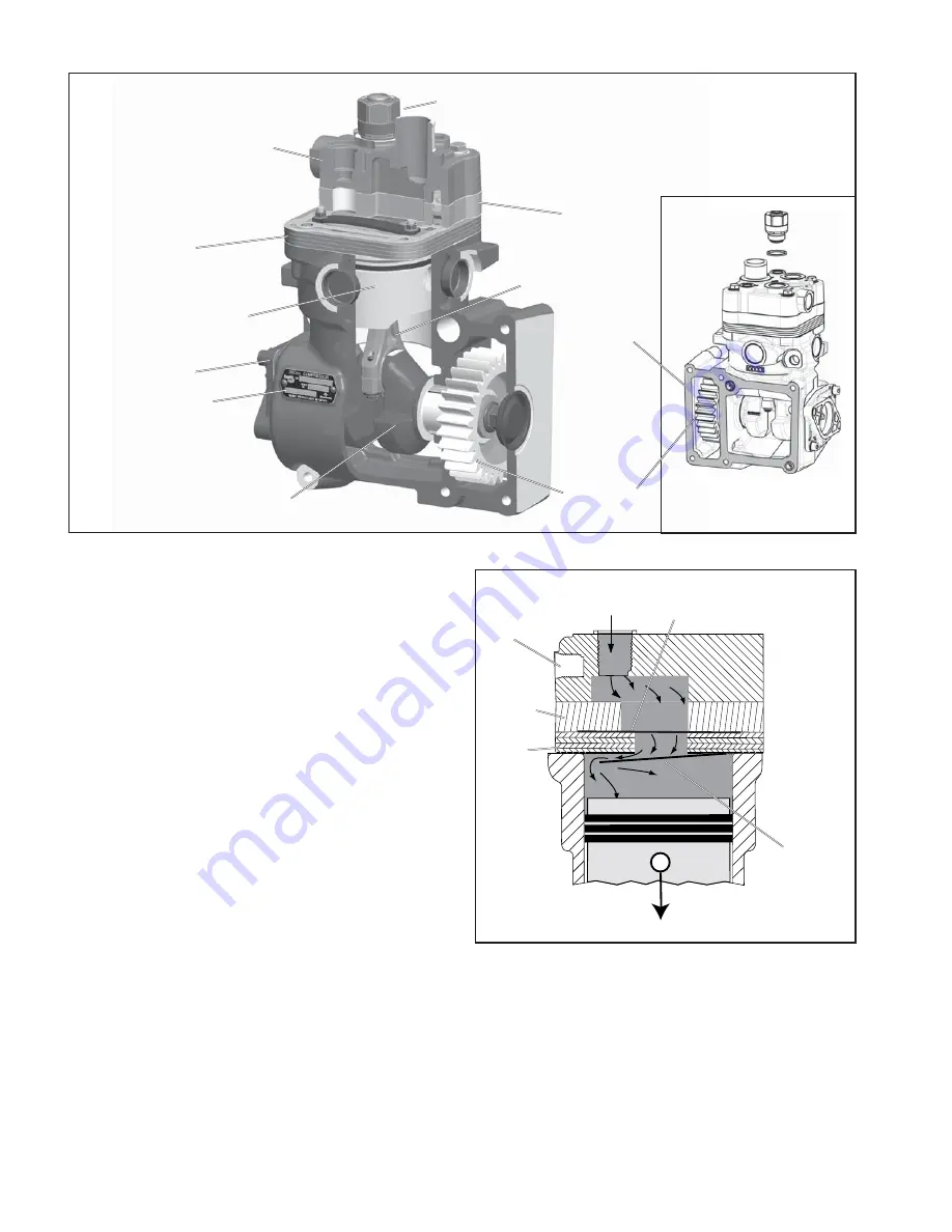
The crankcase has an open side with a machined face
and locating pins. This open face is bolted directly to the
side of the engine block,
see Figure 3.
The compressor
gear engages the engine drive gear. In addition, the
crankcase houses the piston assembly, connecting rod,
crankshaft and related bearings. An o-ring is located in
the countersunk hole on the crankcase deck to seal the
coolant passage between the crankcase and valve plate.
OPERATION
The compressor is driven by the vehicle’s engine and
functions continuously while the engine is in operation.
Actual compression of air is controlled by a downstream
component, such as a discharge line unloader valve or an
air dryer without turbo cut-off valve, operating in conjunction
with a governor.
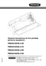
AIR INTAKE (LOADED)
Just as the piston begins the down stroke, (a position
known as top dead center, or TDC), the vacuum created
in the cylinder bore above the piston causes the inlet reed
valve to fl ex open. Atmospheric air fl ows through the open
inlet valve and fi lls the cylinder bore above the piston.
See
Figure 4.
AIR COMPRESSION (LOADED)
When the piston reaches the bottom of the stroke, (a
position known as bottom dead center, or BDC), the inlet
reed valve closes. Air above the piston is trapped by the
closed inlet reed valve and is compressed as the piston
moves upwards. When air in the cylinder bore reaches
a pressure greater than that of the system pressure, the
discharge reed valves open and allow air to fl ow into the
discharge line and air brake system.
See Figure 5.
FIGURE 3 - BENDIX
®
360cc SINGLE CYLINDER COMPRESSOR (CUT-AWAY VIEW)
Safety
Valve
Cooling
Plate
Valve Plate
Assembly
Cylinder
Head
Crankcase
Drive Gear
Nameplate
Piston
Crankshaft
Mounting
Face
Connecting
Rod
FIGURE 4 - OPERATION - INTAKE
Piston Moving Down
Air Inlet
Port
Inlet
Valve
Open
Air
Discharge
Port
Discharge
Valve
Closed
Valve
Plate
Cooling
Plate
Summary of Contents for 360CC
Page 12: ...12 Notes...


