

T M
Document NAE2028421
•
07.2016
•
© Bender Inc.
•
Page 1/1
•
Side 2/2
Bender Inc.
•
USA: 800.356.4266 / 610.383.9200 / [email protected]
•
Canada: 800.243.2438 / 905.602.9990 / [email protected]
•
www.bender.org
LIM2010
Installation Bulletin / Reference Guide
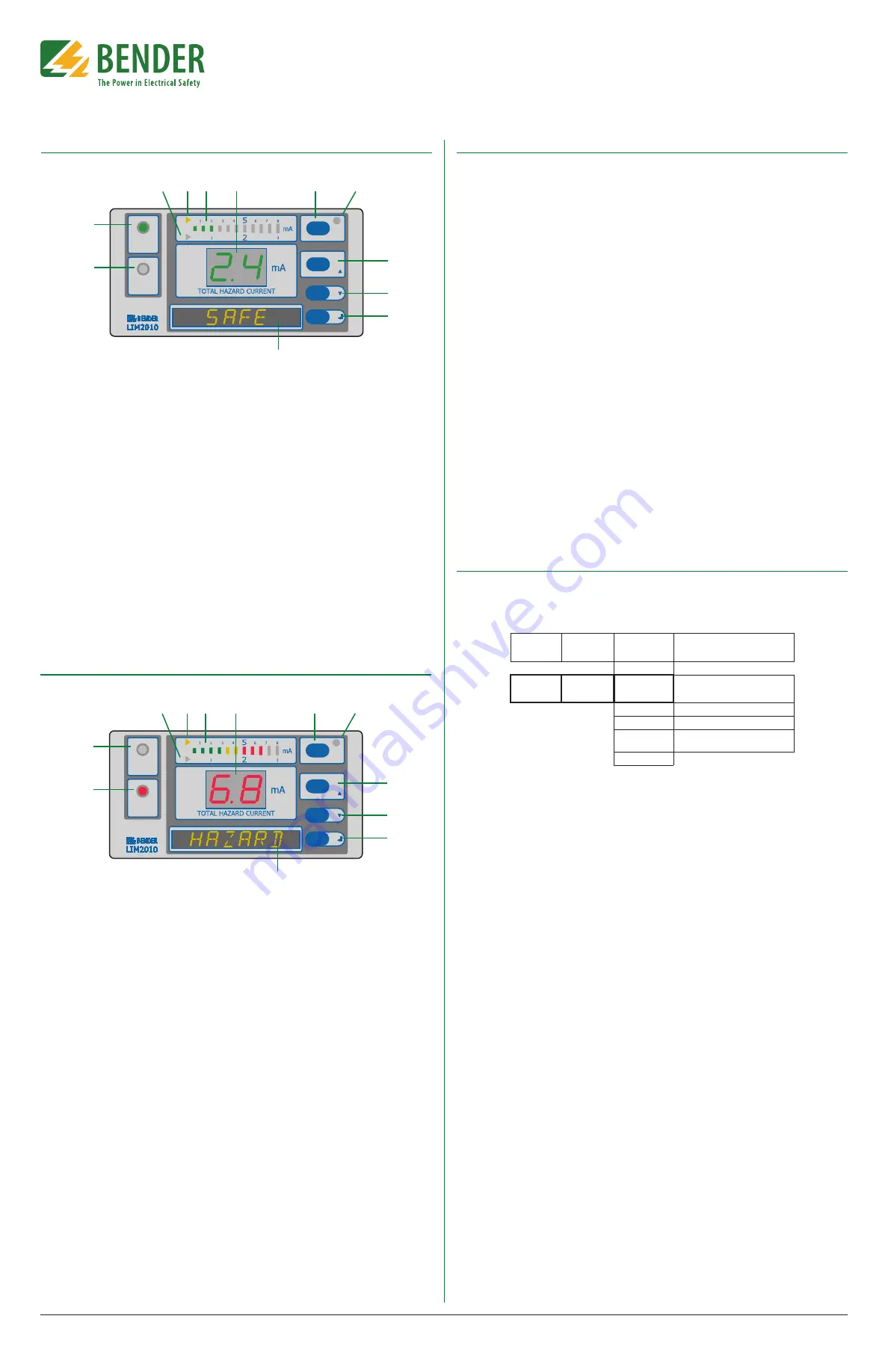
Front Panel Display - Normal Condition
SAFE
HAZARD
MUTE
ESC
TEST
RESET
MENU
1
2
3
4 5
6
7
8
9
10
11
12
1. HAZARD LED (red): Not illuminated.
2. SAFE LED (green): Illuminated. Will be in
the normal condition when the dis-
played Total Hazard Current is below
the set response value (2 mA or 5 mA).
3. Trip value indication light (yellow):
Indicates that the 2 mA trip level has
been activated.
4. Trip value indication light (yellow):
Indicates that the 5 mA trip level has
been activated.
5. LED bar graph: In a normal condition,
only the green bars are illuminated.
6. Seven-segment display of Total Hazard
Current: Green in color for the normal
condition.
7. MUTE button / ESC key: To go to a high-
er level in the built-in menu.
8. MUTE LED: Not illuminated in the nor-
mal condition.
9. TEST button: Activates self-test. / UP
key: To move up in the menu and to in-
crease values.
10. DOWN key: Moves down in the menu
and to decrease values.
11. MENU key: Enters the main menu. /
ENTER key: To confirm entries.
12. Digital display: Reads SAFE in the nor-
mal condition. Also displays menu op-
tions when in the device‘s menu.
Front Panel Display - Alarm Condition
SAFE
HAZARD
MUTE
ESC
TEST
RESET
MENU
1
2
3
4 5
6
7
8
9
10
11
12
1. HAZARD LED (red): Flashes red.
2. SAFE LED (green): Not illuminated.
3. Trip value indication light (yellow):
Indicates that the 2 mA trip level has
been activated.
4. Trip value indication light (yellow):
Indicates that the 5 mA trip level has
been activated.
5. LED bar graph: In the alarm condition,
the red bars will be illuminated.
6. Seven-segment display of Total Hazard
Current: Red in color for the alarm con-
dition.
7. MUTE button / ESC key: To go to a high-
er level in the built-in menu.
8. MUTE LED: When in the alarm condi-
tion, will be illuminated yellow after the
MUTE button has been pressed.
9. TEST button: Activates self-test. / UP
key: To move up in the menu and to in-
crease values.
10. DOWN key: Moves down in the menu
and to decrease values.
11. MENU key: Enters the main menu. /
ENTER key: To confirm entries.
12. Digital display: Reads HAZARD in the
alarm condition.
Figure 4 - LIM2010 in the normal condition
Figure 5 - LIM2010 in the alarm condition
Navigating the Main Menu
Accessing the main menu
Hold the “MENU” button for at least one second. The device will enter into menu mode. The first
item in the menu, “VALUES,” will appear. The number “1” will flash.
Entering the password prior to menu navigation
Many submenu options may be password protected. Passwords are entered as three digit
numbers. The default password is
807
. When applicable, follow the below procedure to enter
the password:
1. A flashing number illustrates which number is currently in focus.
2. Use the UP/DOWN arrow key to select the correct number.
3. Confirm with the ENTER button.
4. Repeat for the next numbers until the last number is confirmed.
5. Settings may now be modified until the menu is exited. Reentering the menu will require
a reentry of the password.
When a parameter is changed and confirmed with the enter key, the change will have an im-
mediate effect. The LIM2010 will continue to operate while settings are modified.
Exiting the menu
Press the ESC key to return to the last step in the menu. Repeat this step until the display has
returned to the main screen. If the LIM2010 is idle in the menu for 5 minutes, the device will
automatically return to the main screen.
Menu structure
Refer to the LIM2010 user manual for a complete diagram of the LIM2010 menu.
Initializing The Clock (Message Code 8.80)
The LIM2010 utilizes date/time stamping. When initially energized, use the menu diagram be-
low to set the date and time. If message code 8.80 appears on the LIM2010, setting the time
and date will clear this alarm automatically.
MENU
Level 1
MENU
Level 2
MENU
Level 3
Meaning
EXIT
4. SETTING 7. Clock
Tm
10.34
A
Time: am/pm
Dy
12/23 Date: month/day
Yr
2011 Year
DST
auto
Daylight saving time: auto/off
(North America time zones only)
EXIT
Figure 6 - Menu structure for changing date and time


