


26
isoUG425_D00220_00_Q_DEEN / 04.2016
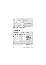
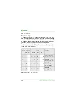
7.1
"AL" menu
Response settings
The response value menu "AL" contains the parameters R1 and R2, which are
used to monitor the insulation resistance. The setting for R1 must be greater
than that for R2. If the value of
R
F
reaches or falls below the active values of R1
or R2, then an alarm message is triggered. The alarm is cleared if R
F
exceeds
the values of R1 or R2 plus the hysteresis value (see table below).
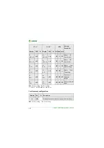
The parameters U < and U > that monitor the mains voltage can also be acti-
vitated or deactivated in the "AL" menu. The maximum undervoltage value is
limited by the overvoltage value.
FAC
= Factory setting;
Cs
= User setting
Display
Activation
Setting
Description
FAC
Cs
Bereich
FAC
Cs
R1 <
R2 … 100
50
kΩ
Pre-alarm value
R
an1
Hys. = 25% / min. 1 kΩ
R2 <
1 … R1
25 kΩ
Alarm value
R
an2
Hys. = 25% / min. 1 kΩ
U <
off
8 … “U>"
8
V
Alarm value
Undervoltage DC
Hys . = 5% / min. 1 V
U >
off
"U<" … 144
140
V
Alarm value
Overvoltage DC
Hys. = 5% / min. 1 V
Summary of Contents for ISOMETER isoUG425
Page 18: ......


