


Page 17
SY
STEMA
TE
2000
2.2 INSTALLATION
2.0 INSTALLATION
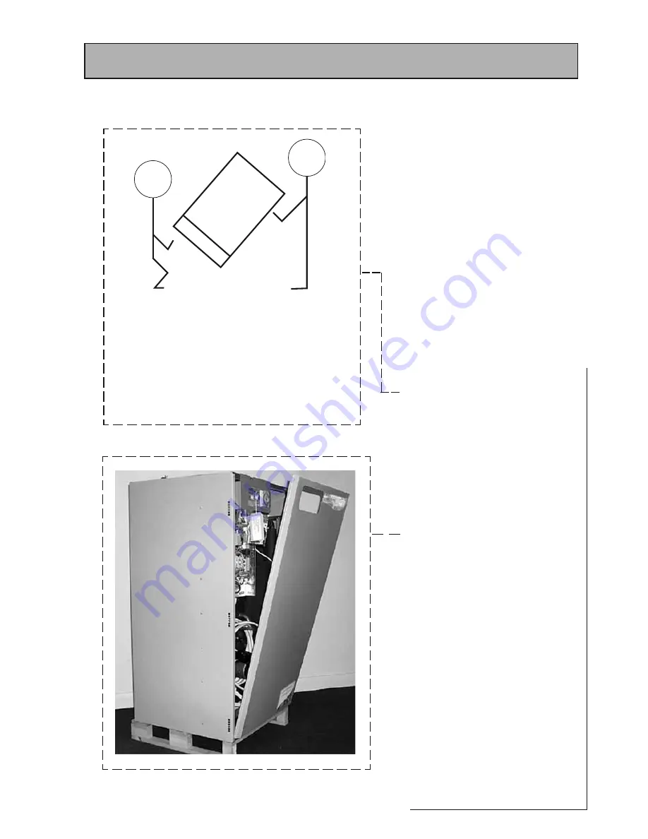
HANDLING
When lifting the unit work with someone of similar build
and height if possible.
Choose one person to call the signals.
Lift from the hips at the same time, then raise the unit
to the desired level.
Move smoothly in unison.
Larger units may need team lift.
Preparation/placing the appliance in
position.
Details of the recommended positions for
termination of the fi rst fi x pipework are provided
in section 1.2 Technical Data. The pipework can be
located or its position checked using the template
provided with each appliance. If these have been
followed installation is very simple and much
quicker than any other system. The appliance is
supplied shrink wrapped on a timber installation
base. Carrying handles are also provided in the
back of the casing.
The feed and expansion cistern complete with
ballvalve, cold feed/expansion and overflow/
warning fi ttings are provided in a separate box
along with the system expansion vessel. If fl exible
connections have been ordered these will also be
inside the feed and expansion cistern.
The appliance should be handled carefully to
avoid damage and the recommended method
is shown opposite. Before installation the site
requirements should be checked and confi rmed
as acceptable. The plastic cover and protective
wrapping should be removed from the appliance
and the installation base (provided) placed in
position.
The appliance can then be lifted into position in
the cupboard on top of the base and the front
panel removed by unscrewing the 2 screws and
lifting the door up and out (see opposite) ready
for connection of the pipework and electrical
supplies. The feed and expansion cistern support
shall be installed ensuring that the base is fully
supported and the working head of the appliance
is not exceeded. The recommended access for
maintenance must also be provided - see section
1.2 Technical Data.
Note: Although the above guidance is provided
any manual handling/lifting operations will need
to comply with the requirements of the Manual
Handling Operations Regulations issued by the
H.S.E.
The appliance can be moved using a sack truck
on the rear face although care should be taken
and the route should be even.
In apartment buildings containing a number of
storeys we would recommend that the appliances
are moved vertically in a mechanical lift.
If it is proposed to use a crane expert advice
should be obtained regarding the need for slings,
lifting beams etc.
A specifi c manual handling assessment is shown in
Appendix D at the rear of this manual.
Summary of Contents for SysteMate 125 97-317-26
Page 39: ...Page 39 SYSTEMATE 2000 APPENDIX D...
Page 42: ...Page 42...
Page 43: ...Page 43 SYSTEMATE 2000...
Page 44: ......