background image

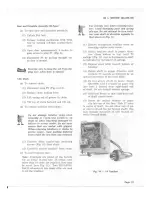
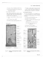
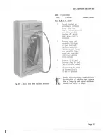
Fig. 20 — Cover Unit With Handset Inverted

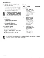
4.03 Preparation

STEP ACTION

Tests A, B, C, D, and E

1 Invert handset on

switchhook (1C-type
only) (Fig. 20)
Note: Prevents armored
cord from pushing
handset off switch-
hook when cover is
removed.

2 Remove cover unit

assembly (1C-type)
or open door and
faceplate assembly

(2C-type) and discon-

nect plug Pl. Place
cover unit assembly

(1C-type) on firm

level surface.

3 Connect P11C cord

between plug P1 and
jack Jl of coin chassis.

4 Ensure that the plug,

on the .totalizer is
in the PP position.

ISS 1, SECTION 506-329-100

VERIFICATION

In the following tests, readout refers
to operation of totalizer and genera-
tion of beeps by coin signal oscillator.
Initial rate set for 10 cents.

Summary of Contents for 1C

Page 1: ...y 36 9 ctllNlNc 96 r coNNEcfloNs 36 t0 L CONVERSTONS 36 l0 to I GENERAT l Ol This sectionincludesidentification instal 13 lation operation tests and trouble anal r ysis maintenance connections and procedures for converting lC and 2C type coin telephone l4 sets to either the prepay PP or dial tone first t5 DTF mode of operation l6 1 02 The convertible lC type coin telephone sets Fig 1 replace the p...

Page 2: ......

Page 3: ...assembly P 90D274dial and housing assembly 85 52 dialf d Replaceable Components for 2C2 Fig 5 1 Components for the 2C2 set are the same as for 2C1 with the following ex ceptions c P 90D275dial and housing assembly 35TgA l2 button TOUCH TONE dial o P 878052 numberplate assembly not re quired el Associated Apparatus for IC Type order separatelu o 2A door 18 or 1C coin receptacle o 1D or 1E coin rece...

Page 4: ......

Page 5: ... e Coin return is designed to deter stuffing f Transmission characteristics of 500 type telephoneset g Arranged to accept 18 or 1C coin recep tacle When larger lC is used false floor in cash compartment must be removed h lD or 1E coin receptacle cover may be used i Electrical connectionsof field replaceable assembliesare made by plug and jack ar rangement except coin relay ringer and coin chassis ...

Page 6: ......

Page 7: ......

Page 8: ......

Page 9: ......

Page 10: ...telg APPlICAT ON lC fype a Refer to Table C Poge lO 2C fype a To fully recessa 2C set in a wall 1 Ensure that the wall will acceptthe set 2 Refer to Fig 3 for dimensions of the set 3 Cut a holein the wall Height 22 1 2 inches Width 16 1 4 inches o Depth 6 inches Ensure that the lip of the faceplate oaerlaps the wall around the hole If securitg studs are used top of hole must be enlarged approximat...

Page 11: ... of Parts a 2 2 l s r4brr Booth a a 2 2 KS 16797 Booth B 19038 Backboard a 2 2 rierer f o Section 508 230 100 KS 19206 Booth KS 19206 List 6 Installation Kit a 2 2 Refer to Section 508 115 200 KS 1926 Shelf a a 2 2 l s ry54u Booth KS 19340 List 53 Backboard a 2 2 lteler f o Section 506 110 105 KS 19425 Booth a a 2 2 l s r942b Mounting ts ti rv4zo List 7 Installation Kit a 2 2 Refer to Section 508 ...

Page 12: ...060 sHotr HREAOS P t0E070 roNG THREADS P 40Y061 3HORr THREAD5 P t2Et98 r oNG TI READ5 l27A t27Z KS 19206 Booth KS 19206 List 7 Installation Kit a 2 2 a KS 19340 Booth KS 19340 List 54 Backboard a 2 2 a Refer to Section 508 111 200 KS 19426 Mounting a a 2 2 Refer to Section 508 470 200 KS 19442 Booth KS 19340 List 54 Backboard a 2 2 a KS 19681 Shelf a a KS 20194 Shelf a a 2 2 Refer to Section 508 1...

Page 13: ......

Page 14: ......

Page 15: ......

Page 16: ......

Page 17: ......

Page 18: ......

Page 19: ...ssembly 1C type or open door and faceplate assembly 2C type and discon nect plug Pl Place cover unit assembly 1C type on firm level surface 3 Connect P11C cord between plug P1 and jack Jl of coin chassis 4 Ensure that the plug on the totalizer is in the PP position ISS 1 SECTION 506 329 100 VERIFICATION In the following tests readout refers to operation of totalizer and genera tion of beeps by coi...

Page 20: ...ition Central ofEce overload TBB not wired conectly Coin relay IIT contact not making Switchhook transfer con tacts SHl NC not making Defective totalizer Defective coin relay Defective chassis Defective handset Defective dial Defective wiring in dial and housing assembly Switchhook contacts SH2 or SH4 not break ing Defective totalizer REI IEDIAT ACTION Reconnect properly Rmonnect properly An overl...

Page 21: ...ly Switchhook contacts SH2 or SII4 NO not mak ing Totalizer set for more than initial rate Defetive wiring in dial and housing assembly T1 contacts NO not making REMEDIAT ACIION Clean contacts or replace dial and housing assembly See Tables K and M Replace dial and housing as sembly Same as Step 5 Same as Step 6 See Tables K and M and Fis 24 or 26 See Table L Replace totalizer Adjust contacts or r...

Page 22: ...iring in dial and housing assembly TB2 not wired correctly TBB not wired correctly Totalizer transfer con tacts T2 NC not mak ing Defective chassis TB2 not wired correctly TBB not wired correctly Totalizer contacts T1 not latrhing lcr EDlAl actlol Replace totalizer See Tables K and M and Fig 24 or 26 Clean contacts or replace dial and housing assembly Replace dial and housing as sembly See Tables ...

Page 23: ...break Totalizer reads out dial tone does not break Coin relay op rates and returns nickel POSSlllECAUSE Ddective dial Defective chassis Defective wiring in dial md housing assenbly Ddective dial Totalizer transfer con tacts T1 NC not break ing TBB not wired conectly Defective chassis Defective chassis II I Renlace defective apparatus Replace dial Coins retum when dial is operated No refund Same as...

Page 24: ...ated in the lower left corner of gauge 9 Reverse the 1468 bias margin gauge by turning it around on the same pole piee extension arm 10 Repeat Step 8 11 Remove 1468 gauge 72 Hang up handset 13 Install dust cover E Coin Tone Signoling 5 Connect leads of 10118 test set to tip and ring terminals on TB1 6 Place TALK MONITOR switch of test set in MONITOR position 7 Lift handset and deposit dime VETIFIC...

Page 25: ... a failure Dime tones too fast Tm many coin tones Quarter tones too slow PO SIBTE CAUSE Totalizer transfer con trcts 51 NC not nak ing Defective chassis Totalizer transf er con tacts CS NC not nak ing or CS cam not re setting Totalizer not stepping properly or contscts T2 NC not naking Totalizer transfer con tacts CS NC not breaking NEMEDIAI ACIION Replace totalizer Replace chassis Replace totaliz...

Page 26: ...andset ProP erly YER FlCAtlot Operator on line cents leturned Ringing heard FAILURE Entrance stop rubs front coYer or does not close entrance to coin chute properly No transmission Coin s not returned No ringing POSSlirEcausE Entrance stoP bent or not adjusted correctlY Def ective transmitt r Defective coin trunk Gong not positioned cor rectly Defective ringer Defective network REIiIEDIAL ACTION A...

Page 27: ......

Page 28: ...ion 5 O l Apparatue Required a PllC Cord Fig 6 b 10118 Test Set or equivalent c Coins 1 penny 2 nickels 1 dime 1 quar ter d 1468 Bias Margin Gauge Fig 19 s Gt Preparation gTEP ACTION VENIFICAIION Tertr A B C ond D 1 Invert handset on switchhook 1C type only Fig 20 Note Prevents armored cord from pushing handset off switch hook when cover is removed 2 Remove cover unit assembly lC type or open door...

Page 29: ...er Initial rate set for 6 cents RET EDIAL ACIIO I Reconnect properly Reconnect properly An overload in the central office may appear to be a fail ure in some instances Before assuming failure allow CO adequatc time to provide line See Tables K and M and Fig 26 or 27 See Table L Clean contacts or replace dial and housing rosembly See Table L 1 Replace defective apparatus J Replace dial and housing ...

Page 30: ...p ring or ground re vened TB2 not wired comectly TB3 not wired correctly Totalizer contact T1 not making Defective chassis Switchhook contact SH3 NO not making Faulty dial Defective chassis TBB not wired correctly Totalizer contacts T1 making for nickel de posit Defective chassis Same as Stcp 6 Initial ret set for more than 10 cents Defetive cont cts Tl in totalizer Defective F contacts in totaliz...

Page 31: ...d in handset of coin telephone One beep heard in test set Five rapid beeps heard in test set relay refunds all FAILURE No beeps heard in test set Beeps heard in coin tele phone handset Note A slight tone may be heard on long loops but may not necessarily be a failure Dime tones too fast Too many coin tones Quarter tones too slow POSStSt E CAUSE TALK MONITOR switch in TALK position Defective totali...

Page 32: ...bent or not adjusted correctly Defective transmitter Defective coin trunk Defective coin trunk TB3 not wired correctly Defective totalizer Defetive chssis Gong not positioned cor rectly Defective ringer Defective n twork REMEDIA ACTION Adjust or replace as neces sary Replace handset Refer to test center Refer to test center See Table L Replace totalizer Replace chassis Position gong for maximum vo...

Page 33: ......

Page 34: ......

Page 35: ...two from TB1 and two from network 4 Remove two ringer mounting screws and lift off ringer 3 Push in and down on bottom of coin return assembly until flush with front 3 Loosen stay hook screw and remove of housing handset cord 4 rnstallcoinreturnassembry lockinE to th il lt l l ii it e rrocedure screw Tighten screvr only enough to hold return assembly in place Further tss I SEcTloN506329 100 b To i...

Page 36: ... Loosentwo mounting screwson sidesof diagrams dial through accessholes in housing 4 Lift dial off 7 O2 Refer to Fig 28 through 31 for schematic olagrams Nofe Before installing a new 8S dial re move and discard the dust cover 8 CONVERSIONS IABTE K DIAI CONNECTIONS IYPE DIAI wtREcotoR CONNECI TO PP DIF Rotary BL TB2 9 TB2 9 G TB2 10 TB2 10 W TB2 2 TB2 2 II TB2 3 TB2 3 Y TB2 9 TB2 9 Y TB2 9 TB2 13 TO...

Page 37: ... IYPE DIA wtRE coloR CONNECI TO OIHER END CONNECTEDTO PP IIOOE DTF litODE Rotary Y TB2 9 TB2 13 DON 2 contact on 8S Dia G TB2 13 TB2 9 sH3 TOUCH TONE V TB2 10 TB2 13 t contact on 35TBA Dial o w TB2 10 T82 9 s contact on 35T3A Dial G TB2 13 TB2 9 SH3 Poge 37 ...

Page 38: ...RK INSULATEANDSTORE COMPONENT BOARD w 81l BR s s BL G Vl S G BK o BK R R S 1 t I I rNsro Rl wrRE l I I IGR iliijj llliiiii COIN REL s s w Y BR 0 wl R G Poge 38 Fig 24 lCl ond 2Cl Prepoy Goin Telephone Sets Conneclions Sheer l TO SH ...

Page 39: ...ONENT SOARD 8 S OIAL tss I sEcTtoN506 329 1 X swrrc xooxii iii G3P 54 HANDsET I 0 I I I w 8L 8X R I l L i sxt I ffi I T t 8R ri O ii i 8R t 1 sH2 lj 1 t j iil i ll l sH4 iii l i I sR trL lL t8K 8L I C tG w sH3 i__ i____ l I tnr z i ii l il_ l l i ii i w 00N r osoLLAToR lnir l lt9 ...

Page 40: ...RK INSULATEAilD STORE TIP R ING GRD iiiiil ii il i i COMPOilEilTBOARD to w B L __lLl_ 8R s s G wt s R R S s s s w Y o w I rNsroE I I t l i i il iii i Poge 4O Fig 25 lCl ond 2Cl Diol Tone Firsl Coin Telephone Sets Connoctions Sheerl ...

Page 41: ...52 HANDSET tiljr tss r sEciloN 506329 100 s Jl T 8 0 _ 5 BR oi 8R 8R BL G I t r Y v R 2 iiiri iiitit ii iNii i iii ll ii J2 P2 6 2 5 to 3 I tl 9 7 nii Iii ro r liiii Fig 25 ICI ond 2cI Diql Tone First coin Telephone Sets Conneclions sheet 2 Poge 4l ...

Page 42: ...i r itj f i ii lf ri tFl ss f ttP t ns oe wrRE l I I GRI t i liii tli i il slr tglil9Jfi fu 1 COITi RELAY x 9 1 ti Jii jii t l jqillliif l i j if i i1 1 G v ffi Poge 42 Fig 26 fC2 ond 2C2 Prepay Coin Telephone Sets Conneclions Sheer l SH ...

Page 43: ...z tar t 2 i R lss I SECTTON 506329 r x vt l t I ll 1 I tf 5 1 FFl r 1 rH r l r r L J r lt L L J u y uJr C Tt RVz RV3 TOTALIZER s vRr Fig 26 lC2 ond 2C2 prcpoy Coin Telephone Sets _ Connections Sheet 2 Poge 43 ...

Page 44: ...ETWORX s c w s r ltP I rNsro I jjlg wrRE I I GR0 t iiil ijliiiliiiiiiiiii i ii iiti ri i riliiiliii ffiiil INSULATE AND STORE iIIIi lis 27 lC2 ond 2C2 Diol Tone First Coin Telephone Pcge 44 c w v ol Setr Connoclionr Shesr l TO SH ...

Page 45: ... F f F r l rH rit lil LL y L J s J Ll I r 1 l cl l r L L COilPONENT Ii iI BoaRD iillli rr iiii tss r sEcrloN505 329 100 It t f l o tig 27 I C2 qnd 2c2 Dic l Tone Firsl Coin Telephone Sets connections Sheei 2 Poge 45 ...

Page 46: ... il iii iit ii i fr i sljiijjiitsi e ii9 r T nl u 8T sHl cR2l U CR2A i i iiX illriliii i i ii l i t lil REI r 02 Rrl 4 Ar i at I I et2 zr I IilIR rcvR TOTALIZ ER RESfI ELECTROfAGTET c6 Rt4 c7 trt i j L t q ir L ilii t 1J iaiil Fi q t i t r r l Tt Llrrc RV3 RV2 R2 R4 RVI5 R7 Fiil ffii ffi l 1 tt iq I u f i tr cRl q D RI R3C 8 R9 I lFt It l A l n i i l ir s IOTALIZER STEPPIM J Iu __t_ 1 T JRV5 tO o1...

Page 47: ...cR2g c6 c7 cRzA ffi u i i Pi nn s TOTALI2ER STEPPING RE LAY CRf A i iirt o o o 5 Fig 29 lCl ond 2Cl Diol Tone Firsf Coin Telephone 5el3 S hemcrtic ...

Page 48: ...IOBNETWORX ji r li ji i ni li E o o z q o or o to o o rnuraffi TOTALIZER RESET LECTROMAGNET TOUCH _TONE OIAL TTo couuon TTb FREoUENcY TTc SHoRTING FOR OTF ONLY Fig 3O lC2 ond 2C2 Prcpay Coin TelephoneSets Schemotic ...

Page 49: ...N SIGNAL OSCILLATOR fi iiiil ii u iia iiiii TTo TRMTR iliiiil iiiiiiiiii iiiiii i il TOTALIZER RESET ELECTROMAGNET 6 E o o z l o I o l9 s C o LN i ts it Fj tal i tii F 1 iriG lc i i 1 ni iiTil iliii tig l iEi illf i ii ji i 1 il5 TOUCH TONE UAL TTo couuor T T b raeoutrcv TTc sxonrno t FT tr Fig 3l lC2 qnd 2C2 Diol Tone First Coin TelephoneSets Schemotic ...

Reviews: