background image

SECTION  502-303-1 01 

LEAD 

NO. 

426N 
DIODE 

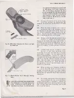
Fig.  12-Typical  Installation  of  426N  Diode  in  Both 

AC1  and  AD1  Bases 

ft 

On 

2-party tip stations requiring ground 

identification,  be  sure  that  the jacks 
and  plugs  are  installed  in  accordance 

with  the  section  on jacks  and  plugs. 

4..  OPERATION 

4.01 

Instruct  the  customer  on  the  necessary 
operating features. 

4.02 

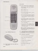
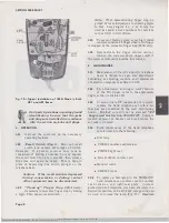
Recall  Switch  (Fig.  1). 

Point  out  recall 

switch  and  explain  advantages  of  switch. 

Example:  If  a  person  receives  busy  tone  at 
conclusion  of  dialing  a  number,  he  may  depress 
the  recall  switch  for  a  few  seconds;  then  release. 

Dial  tone  will  again  be  heard.  This  is  done  in 
place  of  depressing  line  switch  plunger  on  the 
telephone  base. 

Caution:  If  the  recall  switch  is  depressed 

during  conversation  or  dialing,  central 
office  equipment  may  be  disconnected. 

4.03 

"F loating"  Finger  S t o p   220A  o nly: 

Demonstrate moveable finger stop by dialing 

a  digit.  Then  depess  recall switch. 

Page  8 

Note: 

When  demonstrating  finger  stop,  be 

guided  by  local  instructions  in  choosing  digits 
to  dial.  Some  digits  (i.e.,  1  or  9)  may  be 

used  as  special  access  numbers  for  services 
such  as  DDD  in ANI offices. 

4.04 

To  prevent  dialing  errors,  every  digit  dialed 

requires  rotation  of  fingerwheel  until  finger 

is  stopped  by the  moveable finger  stop  (220A  only). 

4.05 

Demonstrate  the  ringer  volume  control. 

Caution  the  customer  about  ringer  cutoff  if 

the screw  is removed  to provide this  feature. 

5. 

MAINTENANCE 

5.01 

Maintenance  of  the  ACl  and  ADl  telephone 
bases  is  limited  to  ringer  bias  adjustment, 

burnishing  or  adjusting  contacts,  and  replacement 
of  defective  components  as listed in 2.05. 

5.02 

For  adjustments  and  ringer  cutoff  feature 
of  the  PIA  ringer,  refer  to  the  appropriate 

ringer  section  in Division 501. 

5.03 

In  areas  where  RF  suppression  is  required, 

replace  the  hand  telephone  set  with  a  set 

that  has  been  modified  by  the  local  distributing 
house.  Modified  sets  will  not  be  stamped 

"RF 

Suppressed  See  Section  500-15(].100". 

Stamp  is 

located  adjacent  to  handset  cord  jack  where  the 
set  code is stamped. 

5.04 

Field  maintenance  of  the  hand  telephone 

sets is  limited  to  the following: 

• 

Dial lamp 

• 

P-25E803 number  card  retainer 

• 

P-28E320 light  seal 

• 

Form E-5002A number  card 

• 

Handset cords 

• 

P-82E800  cover 

5.05 

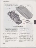
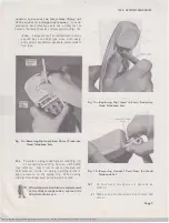
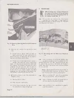
To  replace  a  dial  lamp  in  the  TRIMLINE 

hand  telephone  set, remove cover or  number 

card  retainer,  and  light-seal  plate.  Current 
production  hand  telephone  sets  have  the  lamp  in a 
horizontal  position,  and  a  KS-6320  orange  stick  can 
be  used  to  remove  the  lamp  (Fig.  13). 

Exercise 

BSP  502-3

0

3

-

1

0

1

-

i

03

_

1972

-

09

-

08.jps  Scanned by Frank  Harrell, (Cowboy  Fra11k) Castle  Rock, Colorado  Jan  31, 2012  21:59:48 

Summary of Contents for 1220A

Page 1: ... A and read note 1 01 Add D4BW 29 mountingcord and new handset and mounting cord lengths 1 03 Information on the 1220A MD and 2220B hand telephone sets was formerly found in Sections 502 304 101 and 502 305 101 respectively which are hereby canceled 2 IDENTIFICATION 2 01 The 220A 1220A MD and 2220B hand P 88EO COVER lOA DIAL RECALL t SWITCH ADD COLOR SUFFIX Fig 1 220A Hand Telephone Set telephone ...

Page 2: ...d 25 feet with dial light Cord Mounting D5Alr D5AN 5 feet 6 inches 7 9 13 14 and 25 feet AD1 base Should only be used for 1A1 1A2 and 6A KTS with dial light Note A complete telephone set consist of a hand telephone set base handset cord and mounting cord AD1 base all of which must be ordered separately 2 04 AssociatedApparatus ofEquipment order separately 2012A Transformer for other suitable trans...

Page 3: ...mber card and associated retainer can be used to conceal housing screws and lamp 2 08 ISS 3 SECTION 502 303 101 TABLE B COLOR ORDERING GUIDE STANDARD COLOR SUFFIX Black os Ivory 50 Green 51 Red 53 Yellow 56 White 58 Rose Pink 59 Lt Beige uo Lt Gray Bl Aqua Blue B2 Turquoise B4 Refer to Section 500 120 100 for promoted colors Note Hand telephone sets may be found in the field with a number card or ...

Page 4: ...ith its companion base consider the following Safety for yourself customer and maintenance personnel Page 4 Location desk table wall etc Availability of power outlet for hand telephone set dial light transformer Space requirements General appearance of installation 3 02 The plastic housings of the ACl and ADl bases are secured by captive housing screws located behind the number card and number car...

Page 5: ...osition on ACI Telephone Base 3 04 When inside wire to the AC1 wall telephone base is exposed terminate the line and transformer wiring at a common bridging point such as a 42A connecting block Run one quad station wire from the connecting block to the telephone base Wiring may enter from the opening at the bottom top or through the backplate 3 05 In cases where an inside wire is already in place ...

Page 6: ...n the jacks on each component Page 6 Fig 9 D5AL Mounting Cord 3 09 If tip party identification is required an H5AA cord must be used Check under P 82E800 cover of early production sets to see that screw used in tip party identification switch is tightened down The absence of a screw or screw hole in the identification switch position Fig 10 indicates that the connection has been made in the networ...

Page 7: ... the transformer may result if there is sufficient ground potential difference between power and telephone grounds Refer to appropriate section on bonding to power grounds in Division 460 3 1 5 A 426N diode must be installed in either the AC1 or A D1 base assembly when connecting for 4 party full selective or 8 party semiselective ringing The two leads from the diode are designated No 1 and No 2 L...

Page 8: ...ngerwheel until finger is stopped by the moveable finger stop 220A only 4 05 Demonstrate the ringer volume control Caution the customer about ringer cutoff if the screw is removed to provide this feature 5 MAINTENANCE 5 01 Maintenance of the ACl and ADl telephone bases is limited to ringer bias adjustment burnishing or adjusting contacts and replacement of defective components as listed in 2 05 5 ...

Page 9: ...se a KS 16750 type releaser Insert tool in space provided and hold releaser similar to using a paring knife to apply pressure on the spring clip When spring clip has been depressed pull plug out of jack Iftransmission troublesare experienced or the dial is inoperative replace the hand telephone set ISS 3 SECTION 502 303 101 Fig 1 4 Replacing Dial Lamp in Early Production Hand Telephone Sets F ig 1...

Page 10: ...ONS When making any wiring changes in the bases do not use screws securing terminal board as a bridging point or for storing leads Fig 3 6 01 To restrict the dial on the 220A hand telephone set only place a strap between the pulsing contacts as shown in Fig 17 The dial will remain in the handset Fig 1 7 Restricting Dial of 220A Hand Telephone Set 6 02 Dial restriction of a TOUCH TONE dial equipped...

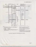
Page 11: ...E WAITING FEATURE 2 LINE SWITCH OFF HOOK SEQUENCE Y LEAD IS NOT TERMINATED IN SET PLUG be CLOSES ab OPENS de CLOSES jk CLOSES 3 DISCONNECT BL LEAD FROM T RMINAL B WHEN HSAA HANDSET CORD IS USED AND TIP PARTY IDENTIFYING GROUND IS NOT PROVIDED INSULATE AND STORE 5 SET IRED FOR INDIVIDUAL OR BRIDGED RINGING FOR All OTHER CLASSES OF SERVICE REFER TO RINGER CONNECTI ON TABLE INSULATEO AND STORED t WHE...

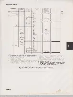
Page 12: ...ET CORD ONLY MESSAGE WAITING LAMP FEATURE Y LEAD IS NOT TERMINATED IN SET PLUG be CLOSES ab OPENS de CLOSES j k CLOSES 3 DISCONNECT S LEAD FROM TERMINAL B WHEN HSAA HANDSET CORD IS USED AND TlP PARTY IDENT FYING GROUND IS NOT PROVI OED INSULATE AND STORE 5 SET IRED FOR INDIVIDUAL OR BRIDGED SERVICE FOR ALL OTHER PARTY SERVICE REFER TO RINGER CONNECTION TABLE INSULATED AND STORED t WHEN USED WITH K...

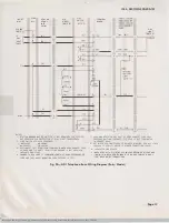
Page 13: ...LUG 2 LINE SWITCH OFF HOOK SEQUENCE be CLOSES ab OPENS de CLOSES jk CLOSES 3 DISCONNECT BL LEAD FROM TERMINAL B HEN HSAA HANDSET CORD IS U5ED AND TIP PARTY IDENTifYING GROUND IS NOT PROVIDED INSULATE AND STORE 4 CHANGE TO 53A LAMP IF COMBINED LENGTH OF HAND TELEPHONE SE CORD AND ADI BASE MOUNTING CORD EXCEEDS 15 FEET 6 SET WIRED fOR INDIVIDUAL OR BRIDGED RINGING F OR ALL OTHER CLASSES OF SERVICE R...

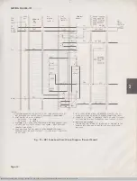
Page 14: ... TIP PARTY IDENTifYING GROUND IS HOT PROVIDED I N5ULATE AND STORE 4 LAMP AND RES ISTOR ARE PART Of HSAD HANDSET CORD ONLY M SSAG WAITI N G LAMP FEATURE Y LEAD IS NOT TERMINHED IN sn PLUG G II G l BK STRAP jG L2 X BR G w R R R 5 SET WIRED fOR INOIVIDU l OR BRIDGED SERVICE FOR All OTHrR PARTY SERVIC E REFER TO RINGER CONNECTION TABLE 6 CHANGE TO 53A LAMP If COMBINED LENGTH OF HAND THEPHON SET CORD A...

Page 15: ...ndset Cord R c c c Jack Leads 220A only G F F F Handset Cord R c c F Jack Leads 1220A 2220B only G F F c Notes 1 If H5AA handset cord is used for other than tip party identifying ground disconnect S ringer lead from terminal B insulate and store Caution Do not store spade tipped leads under terminal board mounting screws 2 To permanently silence ringer move R ringer lead from terminal K insulate a...

Page 16: ...Line Switch QFlanged Gold base 0Knob end housing tip t Insulate and store LEADS OR RING TIP COLOR R R R G G G y y y BK B B R R R G G G y y y BK B B R L2 L2 G L1 L1 y 3 3 BK 1 1 1 L2 L1 2 G G BK 3 3 R K K s B B S R G G BK 3 3 s t t RING TIP R R G G y y B B R R G G y y B B L2 L2 L1 L1 3 3 1 1 3 3 G G 3 L1 K K B B G G L2 L1 t t Caution Do not store spade tipped leads under terminal board mounting scr...

Page 17: ...DIAL LIGHT FEATURES 1A1 1A2 AND 6A KTS SEE NOTES SEE READ IN 1 01 TERMINAL BOARD WIRE OR LEAD COLOR REMOVE CONNECT FROM TO Inside Wire G L1 c or Mtg Cord R L2 L1 Jack Leads G F c Handset Cord W Y B L1 Jack Leads R c F BR c 1 Line Switch y L2 s A Ringer BK L1 c Strap From A BK L2 L1 Notes 1 Install D5AL or D5AN mounting cord 2 Install H5AD handset cord Insulate and store Early bases Fig 18 and 20 C...

Page 18: ...N 1 01 REMOVE CONNECT TO WIRE OR FROM LEAD COLOR TERM POLARITY TERM BOARD GUARD BOARD ASSY Handset R c Term c Cord Jack G F Term F Polarity R c Guard Assembly G F Note For use when specified by local instructions for end to end signaling installations BSP 502 303 101 i03_1972 09 18 jpg Scanned by Frank Harrell Cowboy Frank Castle Rock Colorado Jan 31 2012 22 04 30 ...

Reviews: