B-2
Stinger® MS+ Getting Started Guide
Cables and Connectors
Alarm input port pinouts
Alarm input port pinouts
The alarm input port, found on revision 2 control modules, consists of a DB-15
female connector. This connector provides seven pairs of pins that can be connected
to the alarm relays of up to seven external devices. Operation or nonoperation of
these alarm relays is sensed by the TAOS software, based on continuity or lack of
continuity between the pair of pins to which it is connected.
The sensing connections apply 3.3Vdc at less than 10mA through the closed contacts
of the remote relay. The cable associated with this connector must consist of 24-gauge
to 28-gauge conductors.
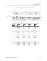
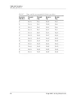
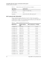
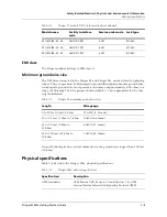
Table B-2 provides the pinouts for the DB-15 alarm input port.
Ethernet interface specifications
The base Stinger unit has an Ethernet interface that supports the physical
specifications of IEEE 802.3 and IEEE 802.14 with Ethernet 2 (Ethernet/DIX)
framing. The unit provides a single Ethernet interface that automatically senses the
Ethernet type to which it is connected. It supports the following types of Ethernet
interfaces:
■
10BaseT (unshielded twisted pair): Twisted-pair Ethernet and IEEE 802.3
(10BaseT) with an RJ-45 connector, labeled LAN UTP
■
100BaseT: 100Mbps baseband modulation on twisted pair
The Ethernet address used to identify the Ethernet interface resides in the [Product]
unit’s motherboard.
To install the Ethernet interface, you must have the cables described in either of the
following two sections.
Table B-2.
Alarm input pinouts
Alarm Relay
Number
Sensing
Connection
Ground Connection
Alarm 1
Pin 1
Pin 2
Alarm 2
Pin 3
Pin 4
Alarm 3
Pin 5
Pin 6
Alarm 4
Pin 7
Pin 8
Alarm 5
Pin 10
Pin 11
Alarm 6
Pin 12
Pin 13
Alarm 7
Pin 14
Pin 15


