


INTUITY CONVERSANT System Version 6.0
MAP/100 New System Installation
585-310-176
Issue 3.0
June 1997
Making Cable Connections
Page 3-17
Connecting the LAN Circuit Card
3
Figure 3-10.
SMC8432 Ethernet LAN Circuit Card Connector
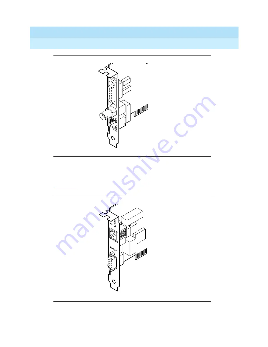
SMC9332 Circuit Card
The SMC9332 Ethernet LAN circuit card is a 10/100-Mbps circuit card.
displays the SMC9332 Ethernet LAN circuit card connector.
Figure 3-11.
SMC9332 Ethernet LAN Circuit Card Connector
cdcvpclb LJK 051497
cdcvpcla LJK 051497


