


800-543-9038
USA
866-805-7089
CANADA
203-791-8396
LATIN AMERICA / CARIBBEAN
40
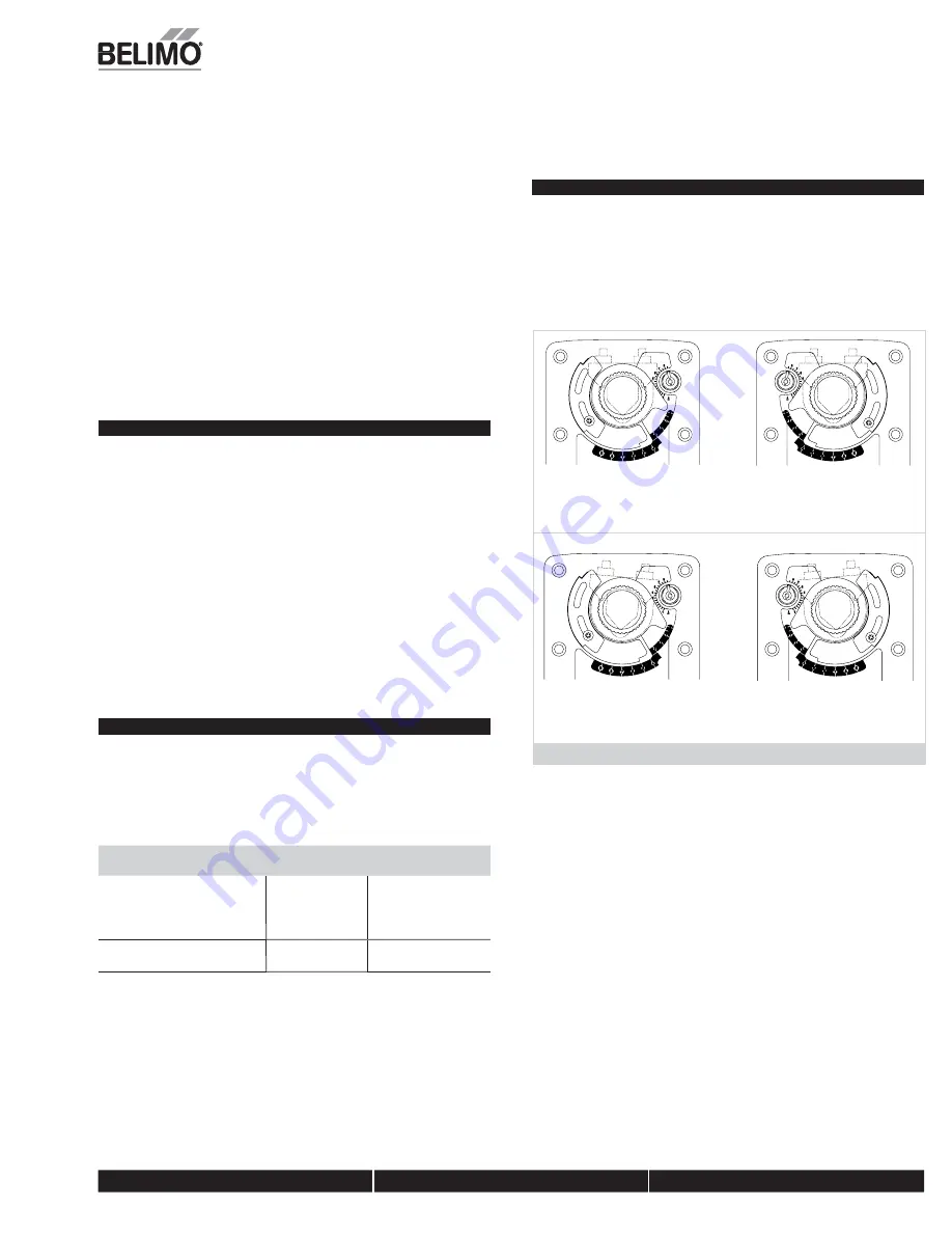
Correct pointer mounting
position if actuator is at
full fail-safe.
Correct pointer mounting
position if actuator is at
5° preload.
Figure A
Installation Instructions
Mechanical Installation
position the clamp so that the pointer section of the tab is pointing to 0° (see
Figure C) and the spline pattern of the clamp mates with spline of the actuator.
Slip the clamp over the spline. (Use the same procedure if the “CW” side is out.)
If your application requires a mechanical minimum position, read the
Rotation
Limiting, Mechanical Minimum Damper Position
section.
n
4. Lock the clamp to the actuator using the retaining clip.
5. Verify that the damper is still in its full fail-safe position.
6. Slide the actuator over the shaft.
7. Position the actuator in the desired location.
8. Tighten the two nuts on the clamp using a 13mm wrench or socket using 11 ft-lb
of torque.
9. Slip the stud of the anti rotation strap into the slot at the base of the actuator.
The stud should be positioned approximately 1/16 of an inch from the closed end
of the slot. Bend the strap as needed to reach the duct. Attach the strap to the
duct with #8 self tapping screws.
Short Shaft Installation
If the shaft extends at least 3/4” from the duct, follow these steps:
1. Determine the best orientation for the universal clamp on the back of the
actuator. The best location would be where you have the easiest access to the V
bolt nuts on the clamp.
2. Engage the clamp to the actuator as close as possible to the determined location.
3. Lock the clamp in place using the remaining retainer clip.
4. Verify that the damper is still in its full fail-safe position.
5. Slide the actuator over the shaft.
6. Position the actuator in the desired location.
7. Tighten the two nuts on the clamp using a 13mm wrench or socket using 11 ft-lb
of torque.
8. Slip the stud of the anti-rotation strap into the slot at the base of the actuator.
The stud should be positioned approximately 1/16 of an inch from the closed end
of the slot. Bend the strap as needed to reach the duct. Attach the strap to the
duct with #8 self tapping screws.
9. If damper position indication is required, use the optional IND-EFB pointer. See
Figure A
.
Jackshaft Installation
The EFB, EFX… series actuator is designed for use with jackshafts up to 1.05” in
diameter. In most applications, the EFB, EFX actuator may be mounted in the same
manner as a standard damper shaft application. If more torque is required than one
EFB, EFX actuator can provide, a second EFB, EFX actuator may be mounted to the
jackshaft.
See wiring guide for wiring details.
EF ACTUATORS WHICH MAY BE USED ON ONE SHAFT
Model
Maximum Quantity
Per Shaft
Minimum Shaft
Diameter
EFB24(-S)(N4)
2*
3/4”
EFX24(-S)(N4)
EFB120(-S)(N4)
EFX120(-S)(N4)
EFB24-MFT(-S)(N4)
3**
3/4” for 2x
1” for 3x
EFX24-MFT(-S)(N4)
* Wired in parellel
** Wired master-slave
MOUNTING:
If the actuators are mounted on the opposed ends of the shaft, the
actuator direction must be selected carefully. Usually, the direction of rotation is
reversed.
Multiple Actuator Mounting
If more torque is required than one EFB, EFX actuator can provide, a second EFB, EFX
actuator may be mounted to the shaft.
NOTE:
The manual positioning mechanism cannot be used in multiple actuator
applications.
Special Wiring and Additional Information: See wiring guide
N40103 - 09/11 - Sub
ject to chan
g
e.
© Belimo
Aircontrols
(USA
), Inc.


