


800-543-9038
USA
866-805-7089
CANADA
203-791-8396
LATIN AMERICA
35
Installation Instructions
Mechanical Installation
Determining Torque Loading and Actuator Sizing
Damper torque loadings, used in selecting the correct size actuator, should be
provided by the damper manufacturer. If this information is not available, the
following general selection guidelines can be used.
Damper Type
Torque Loading
Opposed blade, without edge seals,
for non-tight close-off applications
3 in-lb/sq. ft.
Parallel blade, without edge seals,
for non-tight close-off applications
4 in-lb/sq. ft.
Opposed blade, with edge seals,
for tight close-off applications
5 in-lb/sq. ft.
Parallel blade, with edge seals,
for tight close-off applications
7 in-lb/sq. ft.
The above torque loadings will work for most applications under 2 in. w.g.
static pressure or 1000 FPM face velocity. For applications between this
criteria and 3 in. w.g. or 2500 FPM, the torque loading should be increased by
a multiplier of 1.5. If the application calls for higher criteria up to 4 in. w.g. or
3000 FPM, use a multiplier of 2.0.
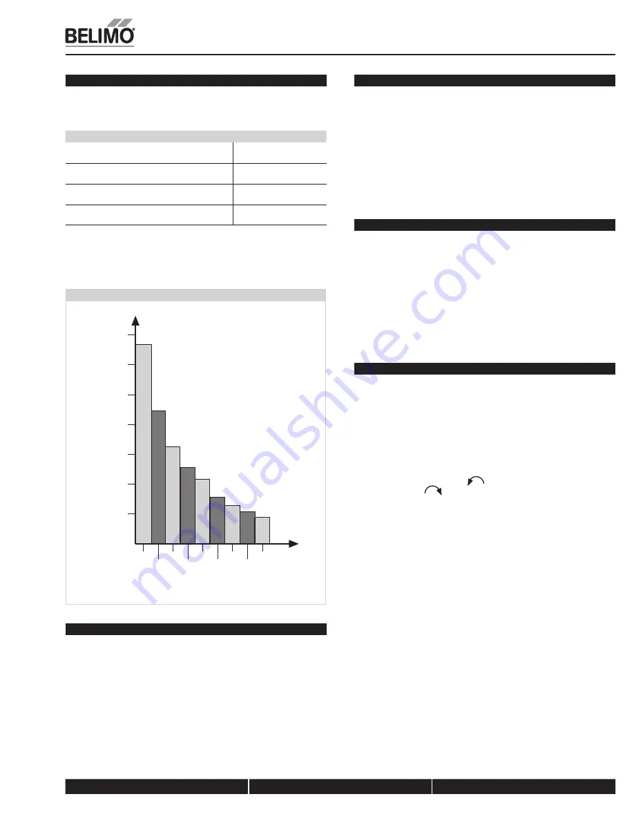
Torque Loading Chart
70
60
50
40
30
20
10
0
2
3
4
6
8
10
5
7
9
Damper Area
(
s
q. ft.)
Torque Loading (in-lb/
s
q. ft.)
General Information
Belimo actuators should be mounted indoors in a dry, relatively clean
environment free from corrosive fumes. If the actuator is to be mounted
outdoors, a protective enclosure must be used to shield the actuator.
For new construction work,
order dampers with extended shafts
. Instruct the
installing contractor to allow space for mounting and service of the Belimo actuator
on the shaft. The damper shaft must extend at least 3 1/2” from the duct. If the
shaft extends less than 3-1/2” or if an obstruction blocks access, the shaft can be
extended with the AV 10-18 shaft extension accessory or the actuator may be
mounted in its short shaft configuration.
Mechanical Operation
The actuator is mounted directly to a damper shaft up to 1.05” in diameter by
means of its universal clamp. A crankarm and several mounting brackets are
available for applications where the actuator cannot be direct coupled to the
damper shaft. The AF series actuators provide true spring return operation for
reliable fail-safe application and positive close-off on air tight dampers. The
spring return system provides constant torque to the damper with, and
without, power applied to the actuator. The AF…-S versions are provided with
2 built-in auxiliary switches. These SPDT switches are provided for safety
interfacing or signaling, for example, for fan start-up. The switching function at
the fail-safe position is fixed at +5°, the other switch function is adjustable
b25 to +85°.
Automatic Airtight Dampers/Manual Override
The AF series provides 95° of rotation and is provided with a graduated
position indicator showing 0° to 95°.
The AF has a unique manual positioning mechanism which allows the setting
of any damper position within its 95° of rotation. A pre-tensioned spring
automatically tightens damper when power is applied to the actuator,
compensating for damper seal deterioration.
The actuator is shipped at +5° (5° from full fail-safe) to provide automatic
compression against damper gaskets for tight shut-off. When power is applied,
the manual mechanism is released and the actuator drives toward the full fail-
safe position.
Standard Mounting
NOTE: The AF…series actuator is shipped with the manual override
adjusted for a +5° position at the universal clamp (not at full fail-safe, 0°).
This allows for automatic compression of damper blade seals when the
actuator is in use, providing tight shut-off. This assumes that the damper is
to have tight shut-off at the fail-safe position. If tight close-off is desired at
the opposite direction from fail-safe, the manual override should be
released so the actuator can go to the full fail-safe position. See the manual
override instructions.
1. Manually move the damper to the fail-safe position (usually closed). If the
shaft rotated counterclockwise (
), this is a CCW installation. If the shaft
rotated clockwise (
), this is a CW installation. In a CCW installation, the
actuator side marked “CCW” faces out, while in a CW installation, the side
marked “CW” faces out. All other steps are identical.
2. The actuator is usually shipped with the universal clamp mounted to the
“CCW” side of the actuator. To test for adequate shaft length, slide the
actuator over the shaft with the side marked “CCW” (or the “CW” side if this
is the side with the clamp). If the shaft extends at least 1/8” through the
clamp, mount the actuator as follows. If not, go to the
Short Shaft
Installation
section.
3. If the clamp is not on the correct side as determined in step #1, re-mount the
clamp as follows. If it is on the correct side, proceed to step #5. Look at the
universal clamp. If you are mounting the actuator with the “CCW” side out,
position the clamp so that the pointer section of the tab is pointing to 0° (see
Figure C
) and the spline pattern of the clamp mates with spline of the
actuator. Slip the clamp over the spline. (Use the same procedure if the “CW”
side is out.) If your application requires a mechanical minimum position, read
the
Rotation Limiting, Mechanical Minimum Damper Position
section.
4. Lock the clamp to the actuator using the retaining clip.
5. Verify that the damper is still in its full fail-safe position.
6. Slide the actuator over the shaft.
7. Position the actuator in the desired location.
8. Tighten the two nuts on the clamp using a 10mm wrench or socket using
6-8 ft-lb of torque.
9. Slip the stud of the anti rotation strap into the slot at the base of the
actuator. The stud should be positioned approximately 1/16 of an inch from
the closed end of the slot. Bend the strap as needed to reach the duct.
Attach the strap to the duct with #8 self tapping screws.
K20901 - 01/09 - Subject to change. © Belimo Air
controls (USA), Inc.