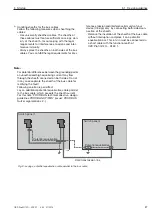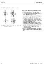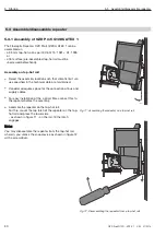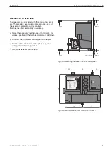
5.8 Connect signal contact cables (optional)
41
5 Startup
OZD Profi G12D... ATEX 1 V. 03 07/2014
z
Warning!
Work on ex-e cables in zone 1 is permitted only
with hot work permit or in the current-free state.
The repeaters are equipped with measuring points for
two analog voltage for diagnosis.
The analog voltage outputs are designed in the protecti-
on class ex-e EN 60079-7:2007. They are placed on the
front side of the OZD Profi G12DU ATEX 1 on three
separate single terminals (CH 2, CH 3 and CH 0V). The
terminals have a valid type approval certificate.
Note
: The terminals are accessible for OZD Profi … DK
… and OZD Profi … DE … after opening the protective
housing.
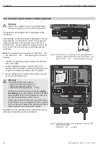
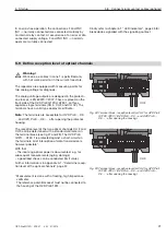
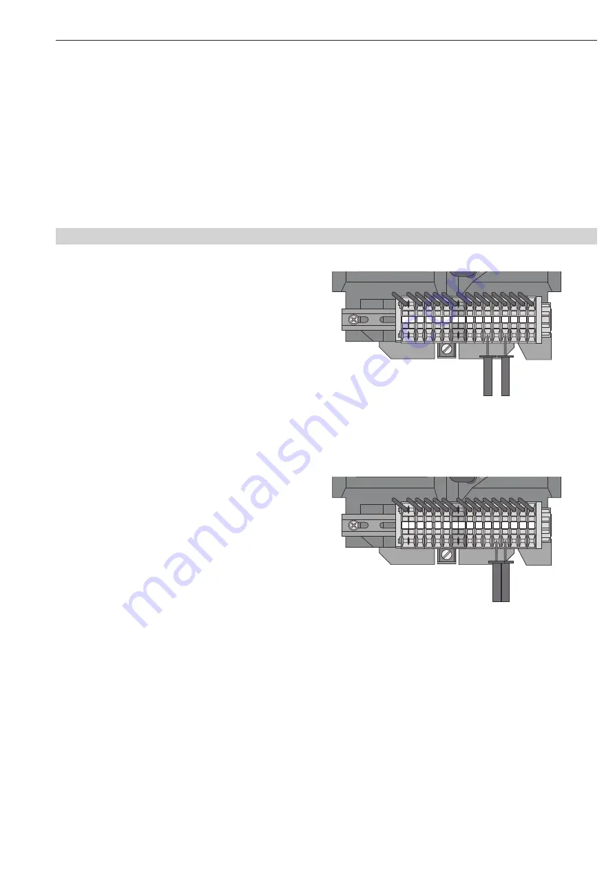
The reception level of the two optical channels CH 2 and
CH 3 can be determined with a standard volt meter on
the terminal block (see fig 27 and 28). The OZD Profi
G12D… ATEX 1 is protected against a short-circuit on
the terminals, brief interruption of data transmission is
however possible*.
With that
– the incoming optical power is documented , e.g. for
subsequent measurements (aging, dam age)
– a good/bad check can be conducted (limit value).
Further information is in appendix A.1, “Determine recep-
tion level of the optical channels“ page 57.
* Measurement is done with a floating, high impedance
voltmeter.
The reference potential socket must not be connected to
the housing of the OZD Profi 12M ….
5.9 Define reception level of optical channels
24
V*
24
V
DI
B
DI
A
0V
0V
FG FG
DO
B
DO
A
CH
0V
F
NC
F
NO
CH
3
CH
2
F
C
H
2
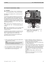
Fig. 28: Terminal block - reception level for CH 2 for OZD Profi
G12DU ATEX 1 (OZD Profi ...DK ... and OZD Profi ...
DE ... : after opening the housing)
24
V*
24
V
DI
B
DI
A
0V
0V
FG FG
DO
B
DO
A
CH
0V
F
NC
F
NO
CH
3
CH
2
F
C
H
3
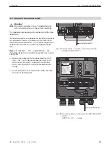
Fig. 29: Terminal block - reception level for CH 3 for OZD Profi
G12DU ATEX 1 (OZD Profi ...DK ... and OZD Profi ...
DE ... : after opening the housing)
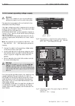
In an error-free operation, the connections F and FNC
(NC -> normally connected) are connected mutually by
an internal relay contact. At occurrence of an error or dis-
connected supply voltage, F and FNO (NO -> normally
open) are mutually connected.
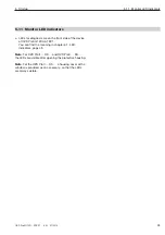
Kindly refer to chapter 6.1 “LED indicators“, page 45 for
breakdowns signalled with the signalling contact.

