


VEA-1023 Analog Video Auto Equalizing DA
Guide to Installation and Operation
Page 2 of 5
VEA-1023
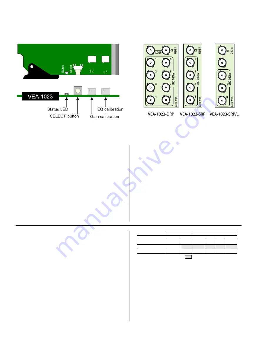
VEA-1023 Front card edge
INSTALLATION
Make sure the following items have been shipped with your
VEA-1023. If any of the following items are missing,
contact your distributor or Grass Valley.
*
VEA-1023
Analog Audio Auto Equalizing DA
*
VEA-1023
-DRP, VEA-1023-SRP or VEA-1023-SRP/L
rear panel
The
VEA-1023
and its associated rear connector panel
must be mounted in a DENSITÉ frame. It is not necessary
to switch off the frame’s power when installing or removing
the
VEA-1023
. See the DENSITÉ Frame manual for
detailed instructions for installing cards and their
associated rear panels.
The
VEA-1023
has multiple inputs and outputs, and
making space for all the necessary connectors at the rear
of the frame requires a double-width rear panel.
When a double–width rear panel has been installed, the
VEA-1023
must be installed in the right-most of the two
slots covered by the panel in order to mate with the panel’s
connectors. If it is placed in the wrong slot, the front panel
LED will flash red. Move the card to other slot for correct
operation. No damage will result to the card should this
occur.
It is also possible to use the VEA-1023 with a single-width
rear panel if fewer outputs are required. This will free up
slots in the Densité frame. Choose the SRP rear panel to
get 4 outputs but no loop-through, or the SRP/L panel to
get three outputs plus the loop-through.
Overview
The DENSITÉ frame incorporates a central controller card,
located in the center of the frame, which is equipped with
an LCD display and a control panel. The controller handles
error reporting and local and remote control for all cards
installed in the frame. The display and control panel are
assigned to the card in the frame whose SELECT button
has been pushed.
Status Monitor LED
The status monitor LED is located on the front card-edge of
the VEA-1023 module, and is visible through the front
access door of the DENSITÉ frame. This multi-color LED
indicates module status by color, and by flashing/steady
illumination, according to the following chart (which also
indicates fault reporting for this card on the DENSITÉ
frame’s serial and GPI interfaces).
REPORT
COLOR (F=flashing)
N.R.M.*
GPI
G
Y
R
FR
No errors
No signal In
Auto Calibrate
: Factory default.
User configurable
* = Non-Requested Messages
A “Flashing Yellow” Status LED indicates that the SELECT
button on the front panel has been pushed, and the
controller display and control panel are now assigned to
this card.
The LED color assignments for some error conditions can
be reconfigured by the user (see the menu for details).
User Interface
Pushing the SELECT button will cause the on-card
STATUS LED to flash yellow, and the card identification
VEA-1023 Rear Connector Panels


