background image

28

Installation

Frame Interface

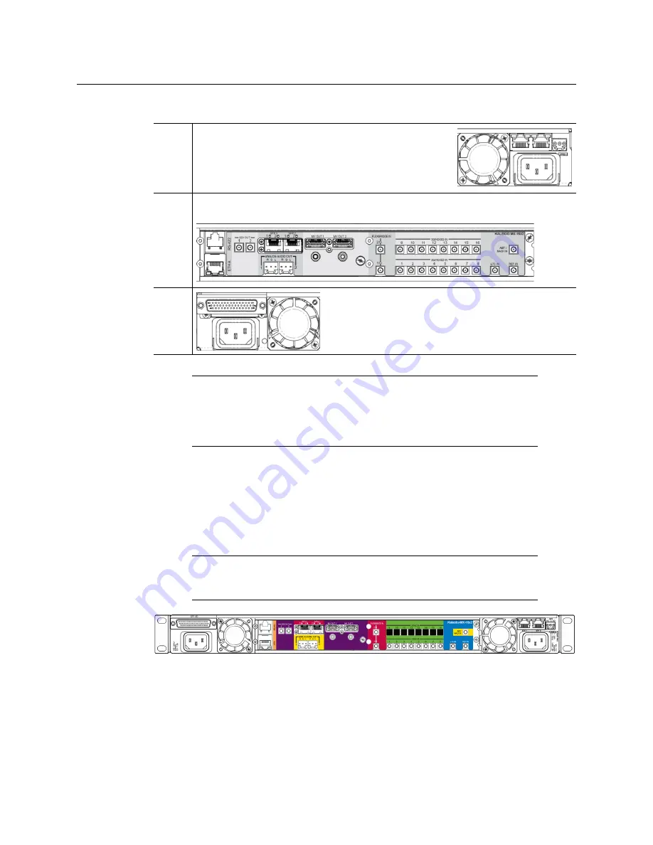
Viewed from the back of the frame, the three sections are laid out as follows:

Kaleido-MX 8 × 1, and 8 × 2

Kaleido-MX systems with 

8 inputs

 are available in single-head and dual-head models. They 

share the same rear-panel layout, including 8 input connectors, 2 HDMI outputs, 2 HD-SDI 
monitoring outputs, 2 analog audio outputs, 1 ABT/MADI audio input, 1 LTC input, 
1 reference input, 1 Ethernet connector, 1 RS-422 connector, 20 GPI inputs, and 
8 configurable GPI input/output.

Kaleido-MX-8x2 rear panel (same panel as Kaleido-MX-16x2)

Kaleido-MX 16 × 1, 16 × 2, and 16 × 4

Kaleido-MX systems with 

16 inputs

 are available in single-head, dual-head, and quad-head 

models.

• The single-head and dual-head models share the same rear-panel layout, including 

16 input connectors, 2 HDMI outputs (one of which is not enabled, in the case of the 

Right

This area contains inputs and outputs for the 

controller


card: the fan speed control setting switch, a GPI port and 
two Ethernet ports. It also contains the power socket for 
the power supply located beneath the controller card, 
and one of the two frame fans.

Center This area contains the connectors associated with your multiviewer’s input and 

output cards.

Left

This area contains the power socket for the power 
supply located beneath the GPI-1501 card, and one of 
the two frame fans.

Note:

The Kaleido-MX (1RU) offers a wide variety of ports for incoming and 

outgoing signals. With a view towards future expansion, there are ports 
whose connections exist but that are currently not fully supported. The 

FlexBridge IN

 ports are reserved for future expansion, and the 

SFP

 ports are 

not yet supported.

Note:

In the case of the HDMI outputs, HD-SDI monitoring outputs, and 

analog audio outputs, in each pair, the output associated with the second 
head is NOT enabled if your Kaleido-MX is a single-head model.

Summary of Contents for GRASS VALLEY KALEIDO-MX 1RU

Page 1: ...Installation Service Manual M933 9902 113 2017 08 11 KALEIDO MX 1RU HIGH QUALITY PRE CONFIGURED MULTIVIEWER...

Page 2: ...hereby grants permission and license to owners of Kaleido Multiviewers to use their product manuals for their own internal business use Manuals for Grass Valley products may not be reproduced or trans...

Page 3: ...ior to making any other equipment connections Identifies an external protective grounding terminal which may be connected to earth ground as a supplement to an internal grounding terminal Indicates th...

Page 4: ...id or aerosol cleaners use only a damp cloth Dangerous voltages may exist at several points in this equipment To avoid injury do not touch exposed connections and components while power is on High lea...

Page 5: ...ischarge occurs when electronic components are improperly handled and can result in intermittent failure or complete damage adversely affecting an electrical circuit When you remove and replace any ca...

Page 6: ...ence dans le texte doit tre remplac par un fusible du m me calibre Identifie une borne de mise la terre de protection Il faut relier cette borne la terre avant d effectuer toute autre connexion l quip...

Page 7: ...s endommager les connecteurs Coupez l alimentation avant de nettoyer l quipement Ne pas utiliser de nettoyants liquides ou en a rosol Utilisez uniquement un chiffon humide Des tensions dangereuses peu...

Page 8: ...parations autres que celles qui sont d crites dans le pr sent manuel sauf si vous tes qualifi pour le faire Confiez les r parations un technicien qualifi La maintenance doit se r aliser dans un milieu...

Page 9: ...tion au moment de vous en d barrasser veillez ce que le cristal liquide n entre pas en contact avec la peau ou la bouche En cas de contact avec la peau ou les v tements laver imm diatement l eau savon...

Page 10: ...his toxic or hazardous substance contained in all of the homogeneous materials for this part is below the limit requirement in GB T 26572 2011 Note This equipment has been tested and found to comply w...

Page 11: ...s Valley Grass Valley Technical explanations This statement is based on the information provided by our suppliers of components and collected through our Grass Valley s environmental management system...

Page 12: ...12 Notices...

Page 13: ...g the Frame 35 Ventilation 38 Kaleido MX 1RU fan speed control 38 3 Multiviewer Cabling 39 Cabling Diagram 39 Signal Connections to the Multiviewer 40 Output Modules 40 System Control 41 Input Modules...

Page 14: ...ling Router Control 73 Uninstalling Router Control 75 Installing Signal Path Viewer 76 Uninstalling Signal Path Viewer 78 Opening XAdmin 79 Connecting to a Multiviewer with a Different XEdit Version f...

Page 15: ...io Bridge Terminal 128 Verifying the Multiviewer s IP Addresses and Application Version 129 Maintenance 131 Required Tools 131 Field Replaceable Units 131 Opening and Closing the Front Door 131 Replac...

Page 16: ...s 155 Video Inputs 8 16 or 24 155 Discrete Audio Inputs 157 Kaleido MX Outputs 158 Kaleido MX Control 160 Reference Inputs 160 LTC Inputs 160 Communication 160 GPI 1501 GPI I O module 161 Kaleido MX 1...

Page 17: ...y s website www grassvalley com docs multiviewers Document Number Title M770 2800 Kaleido Software User s Manual M770 2103 Kaleido Software Release Notes M770 9904 Kaleido Software Product Comparison...

Page 18: ...owing capacities A Kaleido MX multiviewer system in its default configuration includes a number of layout presets Each preset shows the video signals from a specific input module card Refer to the Kal...

Page 19: ...or RCP 200 panels integrated with router control systems and panels iControl and third party control systems Superior layout flexibility Unlimited signal repetition at any sizes across all displays wi...

Page 20: ...do MX system with its inputs and outputs Examples of the various external devices that connect to the Kaleido MX are also shown A control panel would be located on the production desk while the client...

Page 21: ...21 Kaleido MX 1RU Installation Service Manual Functional Block Diagrams Kaleido MX functional block diagram...

Page 22: ...22 Overview Functional Block Diagrams...

Page 23: ...Densit CPU ETH2 controller card and a GPI 1501 GPI I O module and 1 or 2 power supplies second power supply optional Example Kaleido MX 1RU with one input card and one output card The table below indi...

Page 24: ...or system requirements 1RU model WECO connectors 8 1 3 8 2 3 16 1 3 16 2 3 16 4 1 24 1 3 24 2 3 Note Due to space constraints at the 1RU rear panel the 16 4 model does not support analog audio outputs...

Page 25: ...models To connect the multiviewer s SDI outputs to displays Standard coaxial cables with DIN 1 0 2 3 connectors SDI to HDMI 2 0 or SDI to DisplayPort converter for example AJA s Hi5 4K Mini Converter...

Page 26: ...ut cards occupy slots 3 and 4 on the right and an input card occupies slots 1 and 2 on the left The input card itself is inserted in slot 2 at the bottom All dual head models have their output card in...

Page 27: ...r of the Kaleido MX 1RU frame is organized in three sections matching the front Slot Card Card model Applies to 2 Input A KMX 3901 IN 16 Q 16 4 KMX 3901 IN 16 D 16 2 16 1 KMX 3901 IN 8 D 8 2 8 1 Input...

Page 28: ...in the case of the Right This area contains inputs and outputs for the controller card the fan speed control setting switch a GPI port and two Ethernet ports It also contains the power socket for the...

Page 29: ...hich is not enabled in the case of the single head model 2 HD SDI monitoring outputs 2 analog audio outputs 1 ABT MADI audio input 1 LTC input 1 reference input 1 Ethernet connector 1 RS 422 connector...

Page 30: ...local control using the Densit frame s control panel or that the card is booting up See Using the Densit Frame Control Panel on page 48 for details If the Status LED is steady red not flashing use the...

Page 31: ...tatus of the firmware Boot status LED 2 This LED is always red and is currently not relevant Power LED Color Meaning Green OK OFF Failure of the 1 8V or 3 3V on board PSUs SDI LED Color Meaning Green...

Page 32: ...the status of the card by color and by flashing steady illumination The Status LED always shows the most severe detected error status In the table above error severity increases from top to bottom wi...

Page 33: ...munication LED This LED is always OFF and currently not relevant CPU 0 LED not used This LED is always orange and currently not relevant CPU 1 LED Monitors the status of the firmware during the startu...

Page 34: ...EDs Kaleido MX 1RU have 4 or 8 SFP LEDs depending on model located on the rear connector panel These LEDs are always OFF and are currently not relevant Orange Transitory state during firmware initiali...

Page 35: ...uring which time every card s status LED is flashing orange Once the startup has completed the status LEDs on the output cards should be solid red as the cards are not connected to the network yet See...

Page 36: ...ion does not support rotated displays Refer to Creating a 4K UHD Room and to 4K UHD Spanning in the Kaleido Software User s Manual for instructions on how to create 4K UHD rooms and layouts Broadcast...

Page 37: ...s optional but if minimal processing delay is required for your monitoring purposes then you must reference your system However if you must monitor 50 Hz input signals on 60 Hz displays or vice versa...

Page 38: ...be cleaned by rinsing in warm water Dry thoroughly before replacing it in the frame See Replacing the Air Filter on page 143 for details Kaleido MX 1RU fan speed control On the Kaleido MX 1RU frame s...

Page 39: ...39 Multiviewer Cabling This chapter shows how to interconnect the multiviewer with its associated equipment Cabling Diagram Cabling diagram showing the rear view of a Kaleido MX 1RU 16 2 system...

Page 40: ...Connector type Function Head 1 Head 2 MV OUT 1 MV OUT 2 HDMI High definition connection for the multiviewer output which carries audio and video and can support resolutions up to 1920 1200 all progres...

Page 41: ...n RS 422 RJ 45 Connect to an RS 422 SMPTE ST 207 EBU 3245 or RS 485 device or network Notes In the case of the Kaleido MX 1RU 16 4 model there are two Ethernet connectors labelled ETHA for Output A an...

Page 42: ...MX 1RU 16 4 The following table lists the function of each connector associated with the input modules Connector label Connector type Function 3G HD SD IN 1 to 3G HD SD IN 16 DIN 1 0 2 3 SD SDI HD SDI...

Page 43: ...U 24 1 and 24 2 models the sets of 3G HD SD IN connectors associated with INPUT A and INPUT B are labelled as follows 3G HD SD IN A1 to 3G HD SD IN A8 and 3G HD SD IN B1 to 3G HD SD IN B16 see Kaleido...

Page 44: ...Software User s Manual for detailed instructions on configuring a GPI 1501 within your multiviewer system See Related Documentation on page 17 Pin Signal Pin Signal Pin Signal Pin Signal 1 GPIO 1 12 G...

Page 45: ...iagram on page 39 To change the display resolution see Changing the Mosaic Output Resolution on page 52 5 Connect one or more video sources to the multiviewer s inputs see Cabling Diagram on page 39 6...

Page 46: ...eed with the networking setup see Networking Essentials on page 54 IMPORTANT Make sure to connect your Densit controller and output cards to the same subnet and that your Ethernet switch remains isola...

Page 47: ...t of layouts is handled via a Java based application XEdit accessed through a dedicated Ethernet port refer to the Kaleido Software User s Manual see Related Documentation on page 17 Grass Valley s iC...

Page 48: ...r card interface Press the Select button on the front edge of a Kaleido MX input or output card see Card Interfaces on page 29 to assign the local control panel to operate the card The local control p...

Page 49: ...nce signal s refresh rate Parameters shown here in braces will display the actual value of the item and not the text shown above Kaleido MX output card local menu STATUS CARD STATUS CARD VERSION RESOL...

Page 50: ...dly until RESTORE POINTS appears on the display and then press the SEL button 3 Press the button repeatedly until DEFAULT ACTION appears on the display and then press the SEL button If the control pan...

Page 51: ...ve a restore point to the controller s non volatile memory 1 On the Densit frame s local control panel press the CONTROLLER button 2 Press the button repeatedly until RESTORE POINTS appears on the dis...

Page 52: ...LCD display The selected resolution is applied to the multiviewer s output head 1 8 Press ESC to return to the previous level in the local control menu HEAD 1 appears again on the display 9 If you wi...

Page 53: ...ve not applied your change you did not press the SEL button on the local control panel once the 30 second timeout has occurred the parameters will be confirmed as if you had pressed the SEL button Not...

Page 54: ...for each multiviewer See Setting the Multiviewer s IP addresses on page 54 Configuring the RCP 200 if available See Configuring the RCP 200 on page 111 Configuring the Kaleido RCP2 if available See Co...

Page 55: ...for example If you have a single head or a dual head Kaleido MX then replace the IP address for Output A with an appropriate IP address and change the network mask and default gateway as appropriate...

Page 56: ...n and XEdit from a client PC or laptop within the same subnet and verify your system communication status see Multiviewer Model Representation in XEdit and XAdmin on page 67 and System Verification on...

Page 57: ...ol panel s display 6 Press the button NETWORK MASK appears on the control panel s display 7 Repeat step 4 and step 5 to configure the netmask 8 Once you have set the network mask press the button agai...

Page 58: ...tion to the right Press ESC to move one position to the left 5 When the display shows the desired value press SEL repeatedly until you reach the last position if needed and then press SEL once more to...

Page 59: ...tus LED again and make sure that it does not indicate an error condition See Output card Status LED on page 32 Should the Status LED indicate an error condition see Card Interfaces on page 29 to find...

Page 60: ...and return to the previous menu level FRAME IP ADDRESS EDIT appears on the control panel s display 5 Press the button NETMASK EDIT appears on the control panel s display 6 Repeat step 3 and step 4 to...

Page 61: ...h time the cards Status LEDs are first red and then flashing orange 19 Once the startup has completed check both cards Status LEDs again and make sure that they do not indicate an error condition See...

Page 62: ...iewer There is no mechanism provided for changing the default settings Port Used for Transport Notes 443 HTTPS TCP Used by XAdmin for secure access 7 HTTP TCP Used by XEdit for ping probing 80 TCP Use...

Page 63: ...tion 8084 TCP Internal communication 8085 TCP Internal communication 8086 TCP Internal communication 8087 TCP Used for debugging purposes 8090 TCP Web service 32769 TCP filenet rpc 5120 UDP On multica...

Page 64: ...Transport Notes 25 SMTP TCP Simple Mail Transfer Protocol for e mail alerts 8851 Alpermann Velte TCP Used to obtain information from Plura Alpermann Velte Studio Production Timer SPT systems 5100 GPI...

Page 65: ...onfigurable in XEdit you can choose any UDP or TCP IP port to use for communications between the multiviewer and an external router Port Used for Transport Notes 161 SNMP UDP Used for SNMP Simple Netw...

Page 66: ...g you to cancel the operation and try again later when all cluster members are available However in the advent that such a change was made by mistake or that it as been forced for some reason you will...

Page 67: ...and then export your changes to the multiviewer If you have only one multiviewer or if you have more than one but you intend to always have the same version of the Kaleido Software on all of them down...

Page 68: ...e appears 2 Click the XEdit button The browser prompts you to save an executable file to your hard drive Kaleido windows32 online exe1 This file is an online installer which will download XEdit and ot...

Page 69: ...hortcuts are added to your desktop and to the Start menu under All Programs If you have Windows 8 1 or Windows 8 XEdit will appear on your desktop in the Apps view with all the other applications on y...

Page 70: ...ase a message will appear to confirm the font update and instruct you to restart the application Click OK to continue and then open XEdit again by using the shortcut on your desktop in your Apps view...

Page 71: ...ion on page 17 Note Once it has been installed from the multiviewer XEdit remains on your PC or laptop and can be launched from the shortcut that was added to your desktop Apps view or Start screen se...

Page 72: ...ows you may have open 2 Locate the Uninstall XEdit shortcut If you have Windows 7 or Windows 10 Open the Start menu click All Programs scroll to the Grass Valley or Miranda Technologies2 folder and th...

Page 73: ...The browser prompts you to save an executable file to your hard drive Kaleido__RouterControl windows32 online exe3 This file is an online installer which will download Router Control and other compan...

Page 74: ...d the Router Control main application window appears The application automatically connects to your multiviewer The main window lists all logical routers configured within your multiviewer system in a...

Page 75: ...e launched from the shortcut that was added to your desktop Apps view Start screen see page 73 or from the Start menu Whenever you install a new version of the Kaleido Software on the multiviewer the...

Page 76: ...wser prompts you to save an executable file to your hard drive Kaleido__SignalPathViewer windows32 online exe4 This file is an online installer which will download Signal Path Viewer from your multivi...

Page 77: ...indows 8 Signal Path Viewer will appear on your desktop in the Apps view with all the other installed applications on your PC Windows 8 1 or in your Start screen Windows 8 Once the installation has co...

Page 78: ...k Uninstall Signal Path Viewer An uninstall screen appears 4 Click Uninstall Notes Once it has been installed from the multiviewer Signal Path Viewer remains on your PC or laptop and can be launched f...

Page 79: ...your PC Under this circumstance proceed as follows There is no compatibility problem if only the patch revision number is different between the Kaleido Software version on the multiviewer and the XEdi...

Page 80: ...page 81 Internet Explorer users may also need to enable compatibility view see Enabling the Compatibility View in Internet Explorer on page 90 Opening XAdmin from a Browser To open XAdmin from a brows...

Page 81: ...area on the left side of the page Registering your Multiviewer s Security Credentials with your Browser When you open your multiviewer s home page or try to access XAdmin your browser may report a ce...

Page 82: ...rity Credentials with your Browser To register your multiviewer s security credentials with Firefox 1 Click I understand the Risks at the bottom of the page The message expands 2 Click Add Exception 3...

Page 83: ...ut seeing the warning This will remain effective until the multiviewer s IP address is changed in which case you will need follow the procedure again Suppressing certificate error in Internet Explorer...

Page 84: ...84 System Configuration Registering your Multiviewer s Security Credentials with your Browser Internet Explorer s security warning Chrome s security warning...

Page 85: ...er 1 Click Continue to this website not recommended The address bar now indicates the certificate error 2 Click Certificate error 3 In Untrusted Certificate click View certificates 4 In Certificate cl...

Page 86: ...ion Registering your Multiviewer s Security Credentials with your Browser 5 In Certificate Import Wizard click Next 6 In Certificate Import Wizard click Place all certificates in the following store a...

Page 87: ...87 Kaleido MX 1RU Installation Service Manual 7 In Select Certificate Store select Trusted Root Certification Authorities and then click OK 8 Back in Certificate Import Wizard click Next...

Page 88: ...88 System Configuration Registering your Multiviewer s Security Credentials with your Browser 9 Click Finish A security warning appears...

Page 89: ...then click OK to close the Certificate window 13 Close all Internet Explorer and Chrome if any windows and then open your browser again You should now be able to access XAdmin from your multiviewer ho...

Page 90: ...To enable the compatibility view for your multiviewer s XAdmin Web client Click the Compatibility View button at the end of your browser s address bar XAdmin s Status and Options page appears The Com...

Page 91: ...n area on the left side of the page The Access Control page appears 3 Type the password you want to enforce in both the New password and the Confirm boxes The password must contain between 6 and 20 al...

Page 92: ...s and Options page appears 9 Click Log out when you are ready to close you session A confirmation message appears 10 Click OK The login page appears Only authorized users have access to XAdmin Changin...

Page 93: ...rmation message appears 5 Click OK to close the message window The Apply settings button becomes available 6 Click Apply settings XAdmin must upload the password to the multiviewer for the password ch...

Page 94: ...le access control A confirmation message appears 4 Click OK to close the message window and then click Apply settings A progress indicator appears momentarily followed by a confirmation message 5 Clic...

Page 95: ...ation To view the status information for a multiviewer 1 Open XAdmin See Opening XAdmin on page 79 XAdmin s Status and Options page appears showing the multiviewer model and a list of all modules and...

Page 96: ...a module s heading row to view more detailed information about this card or multiviewer At any time you can click the Refresh button to make sure the data displayed for the selected module is up to d...

Page 97: ...or more information about Kaleido Software options see Available Hardware and Software Options on page 122 5 If your system supports a GPI interface check the main system statuses of the multiviewer t...

Page 98: ...h XAdmin To change your system s IP address and other parameters 1 Open XAdmin See Opening XAdmin on page 79 2 Click System configuration in the navigation area on the left side of the page The System...

Page 99: ...nd time in the applicable format 5 Enter the appropriate IP information frame or card IP addresses network mask and default gateway By default all network adapters are set to auto negotiate The connec...

Page 100: ...ou to reboot the system immediately 10 Click OK You will need to edit the XAdmin URL in your Web browser s address bar in order to log on to the multiviewer again Note As required by the IEEE 802 3 st...

Page 101: ...7 In iControl Navigator iControl Web or iControl Solo double click the icon for a Kaleido MX input or output card KMX 3901 OUT KMX 3901 IN 8 D KMX 3901 IN 16 D or KMX 3901 IN 16 Q to open the associat...

Page 102: ...e housing frame see Using the Densit Frame Control Panel on page 48 The navigation area contains buttons that control the contents of the main area Click a button to access the associated features Cli...

Page 103: ...ts characteristics to the Kaleido MX multiviewer via the HDMI connector the matching can be done automatically in which case the detected resolution appears in the Detected resolution box Select the c...

Page 104: ...tion Format name Refresh rates Hz 1024 768 XGA 50 00 59 94 1280 720 Margay 50 00 59 94 1280 768 WXGA 50 00 59 94 1280 1024 SXGA 50 00 59 94 1280 1024 BARCO 59 94 1360 768 NEC 50 00 59 94 1480 1200 Chr...

Page 105: ...rnet port of the Kaleido MX output cards not to the Ethernet ports at the back of the Densit controller card On all Kaleido multiviewers the network adapters are set to auto negotiate By default the c...

Page 106: ...ke this card easier to identify in a complex setup The remaining boxes show manufacturing information about this card Label Type a label to identify this Kaleido MX card when it appears in iControl ap...

Page 107: ...e iControl network Remote system administration Opens the Joining Locators window which lists remote lookup services to which this Kaleido MX card is registered Click Add to force the iControl service...

Page 108: ...119 2 Open a Web browser window and enter the multiviewer s system IP address in the address bar see Finding the System IP Address on page 129 if needed 3 The Kaleido Multiviewer s home page appears...

Page 109: ...uplex mode settings information about your housing frame the input cards and the output card you are currently connected to as well as date and time settings 9 Under General type the name you wish to...

Page 110: ...configuration to take effect A message appears prompting you to restart the system immediately 13 Click OK Note Under Ethernet you may review the IP addresses network mask gateway settings and the de...

Page 111: ...ur control knobs in the CHANGE area to set the new address The current address is displayed in the CURRENT box for reference and the new address you are setting appears in the MODIFIED box as well as...

Page 112: ...and ROOM1 includes displays fed by both multiviewers then both KX1 ROOM1 and KX2 ROOM1 will be listed To determine the one you should select review the following Has the RCP user configuration you wan...

Page 113: ...egory becomes selected instead of ASSIGN CHANNEL and the right hand screen shows the message prompting you to select a router from the left hand screen prefixed with the name of the multiviewer which...

Page 114: ...s KX Router logical router In the case of a cluster system you will also be prompted to select a router the first time to try to assign a source to a monitor located in a part of the layout that belo...

Page 115: ...191 Assigning a static IP address to the Kaleido RCP2 To assign a static IP address to the Kaleido RCP2 1 Press and hold the ENTER button until the ESC button lights up to display the configuration me...

Page 116: ...e 2 key to move up in the list or the 8 key to move down the list 4 When the appropriate room name is highlighted press ENTER to accept the new selection 5 When prompted log on to the selected room Se...

Page 117: ...edure To log on to a Kaleido Multiviewer system from the Kaleido RCP2 1 Press the LOGIN key The following message will appear on the LCD display LOGIN Position Admin 2 Press ENTER to select Admin A me...

Page 118: ...e multiviewer s input modules For more information refer to the Audio Bridge Terminal Guide to Installation and Operation see Related Documentation on page 17 To configure the IP address and other net...

Page 119: ...s network settings as necessary and then click Apply Reboot For more information about the ABT refer to the Audio Bridge Terminal Guide to Installation and Operation see Related Documentation on page...

Page 120: ...ck the network adapter you wish to configure e g Local Area Connection or Ethernet and then click Properties If the system prompts you for an administrator password or confirmation type the password o...

Page 121: ...P address For example if the ABT s IP address is 10 0 3 190 then the IP address of your client PC could be 10 0 3 1 If you are unsure contact your network administrator 7 Type a subnet mask in the sam...

Page 122: ...CC XDS KMX IN 8 OPT CSX CC subtitling and XDS data license 8 inputs KMX IN 16 OPT CSX CC subtitling and XDS data license 16 inputs The extraction of CC 608 CC 708 XDS and Subtitling WST metadata are...

Page 123: ...w that corresponds to the module for which you want to enable an option 4 Locate the entry for the option you want to enable For example to activate the Extraction of CC Subtitling and XDS metadata op...

Page 124: ...System Configuration Enabling Options 6 Enter the key for the specific option in the box and then click OK Once the option is enabled the key is displayed and a Disable button replaces the Enable but...

Page 125: ...quad head system in the address bar The Kaleido Software home page appears 2 Click the XAdmin button 3 If you see a security warning or a certificate error message then see Registering your Multiview...

Page 126: ...d indicates the location where a problem was detected 8 Click Status and options in the navigation area on the left of the page to go back to the Status and Options page The module headings show the c...

Page 127: ...Kaleido RCP2 is functioning normally Log on to the Kaleido RCP2 see Configuring the Kaleido RCP2 on page 115 and then test various operations using the Kaleido RCP2 keyboard and the mouse e g load a p...

Page 128: ...o the Kaleido Software User Manual to learn how to customize the Kaleido IP to suit your specific needs See Related Documentation on page 17 Verifying the Audio Bridge Terminal To verify that the ABT...

Page 129: ...XEdit and XAdmin 4 Press the Select button on the front edge of the output card to exit the control menu Verifying an Output Card s IP Address and Application Version To verify the IP address and app...

Page 130: ...Application Version To verify the application version on an input card 1 Press the Select button on the front edge of the Kaleido MX input card See KMX 3901 IN Front Card edge Description on page 29...

Page 131: ...iscellaneous hardware Available Options on page 19 There are no user serviceable parts within these components except that cooling fans can be replaced on some cards and in some frame components See C...

Page 132: ...swivel handle on the front of the card you wish to remove to lever the connectors apart and then use the handle to pull the card straight out of the slot 3 Close the front door of the frame see Closin...

Page 133: ...ilt the swivel handle on the front of the card to lever the connectors apart and then use the handle to pull the card straight out of the slot 3 Slide the new GPI 1501 card into the slot with the swiv...

Page 134: ...roller Card below 3 Remove the power supply module by pulling on the handle on its front panel and sliding it out of the frame 4 Slide the new power supply module into the slot and push it gently into...

Page 135: ...his can cause unexpected behavior such as glitches or even a system freeze or shutdown The multiviewer self diagnoses high temperature conditions by raising critical temperature and fan alarms Critica...

Page 136: ...ust be addressed right away During off hours when the system is not in use eject the card or if possible the module from the multiviewer s frame and inspect the fan assembly remove any accumulated dus...

Page 137: ...for a fan in some modules the entire fan assembly must be replaced Fans are located on certain cards and within the multiviewer s frame To replace a fan on a card see Replacing KMX 3911 Card Fans on...

Page 138: ...ower connector shown in the tables below for XEdit to be able to correctly identify the specific fan that has failed XEdit Fan Fail Alarm Applies to model Uses Power Connector KMX 3901 IN 8 D KMX 3901...

Page 139: ...ve Required Tools The following field supplied material is required Compressed air to remove dust from the card Flashlight to perform a visual inspection to confirm fan rotation Phillips screwdrivers...

Page 140: ...ltiviewer s frame See Replacing Cards on page 132 2 Place the card on an anti static bag or anti static work surface 3 Using curved tweezers disconnect the fan power connector plug very carefully gent...

Page 141: ...accumulated dust from the card with compressed air 7 Replace the fan with the new one and replace all screws in the reverse order 8 Route the fan s power wires through the wire holders and make the c...

Page 142: ...panel pushing it straight in and ensuring that the connector on the assembly mates with the socket in the frame The two ventilator fans are mounted at different angles as shown in the above figure 3 A...

Page 143: ...ter into the slot at the bottom of the front panel door and ensure that the filter is not bunched or folded 2 Close the front panel of the frame see Closing the front door on page 132 Generating a Sys...

Page 144: ...RTANT Back up your system database Before upgrading the multiviewer system make sure you have a backup of the current system database Refer to Creating a Backup in the Kaleido Software User s Manual f...

Page 145: ...ll be required on page 150 Upgrading a Kaleido MX from version 7 50 or earlier Version 7 51 of the Kaleido Software introduced a change in the location of URS time code information in the system repre...

Page 146: ...ch could result in alarms being raised earlier and more frequently after upgrading The following properties have been removed from the list of configurable parameters Occurrences and Detection window...

Page 147: ...n click Select 7 When prompted to select an update file locate and open the following Kaleido Software operating system file kmxos 8 60_build_xxxx os The os file will be copied to the USB key This may...

Page 148: ...d that you can use the mouse to move the pointer on the monitor wall If the mouse is unresponsive try rebooting the Kaleido RCP2 by pressing ENTER ESC DEL on the Kaleido RCP2 s keypad If your system d...

Page 149: ...ntire upgrade process has successfully completed a red button appears at the bottom of the dashboard on all displays that are connected to the system IMPORTANT To cancel the upgrade process you must c...

Page 150: ...card d Once the master card s startup process has completed reseat all other cards At this point the system will recognize that the Kaleido Software version on some cards does not match the master car...

Page 151: ...r wall and then click Show dashboard to display the dashboard associated with the current head Monitor wall menu within composite monitor menu After a brief delay the dashboard appears at the bottom r...

Page 152: ...lity Kaleido MX multiviewers housed in a Densit frame with a controller card that has version 2 2 0 or later of the CPU ETH2 firmware cannot be downgraded to a Kaleido Software version earlier than 7...

Page 153: ...output card Duplicate frame IP address Another equipment on the network shares the same IP address as the multiviewer system in a multiple output card setup Ethernet Link Down The output card to which...

Page 154: ...154 Maintenance Troubleshooting Dashboard Messages...

Page 155: ...elds if the video inputs are genlocked and two or three fields if the video inputs are not genlocked In rotation mode the processing delay may increase by one field Signal inputs require DIN 1 0 2 3 c...

Page 156: ...loss 15 dB up to 1 5 GHz Alignment jitter 100 kHz 0 2 UI Timing jitter 10 Hz 1 UI Cable length 100 m 328 ft Belden 1694A 45 m 148 ft Belden 1855A 3G SDI inputs Signal SMPTE ST 424 2 97 2 97 1 001 Gbps...

Page 157: ...ronous with video reference signal Return loss 15 dB 100 kHz to 125 MHz Cable length 100 m 325 ft Belden 8281 or Belden 1694A Connector Coaxial via DIN 1 0 2 3 75 ABT audio inputs Signal SMPTE ST 259...

Page 158: ...es 50 Hz and 59 94 Hz Audio PCM 24 bits Cable length 15 m 50 ft with Gefen CAB HDMI 50MM Connector HDMI type connector Signal path 24 bits RGB HD SDI monitoring outputs Signal SMPTE ST 292 1 1 485 1 4...

Page 159: ...2 97 1 001 Gbps Formats Level A only 1080p 50 Hz 1080p 59 94 Hz Audio SMPTE ST 299 1 limited to one pair embedded on group 1 pair 1 Return loss 15 dB up to 1 5 GHz 10 dB up to 3 GHz Alignment jitter 1...

Page 160: ...synchronization Communication Reference Input Supported formats SMPTE ST 170 SMPTE ST 318 ITU 624 4 BT 470 6 SMPTE ST 274 SMPTE ST 296 Connector DIN 1 0 2 3 LTC Input Signal SMPTE ST 309 1999 SMPTE ST...

Page 161: ...tor DB 44 Pull up voltage 2 3 Volts Source current 2 mA when input shorted Low level activation 0 8 Volts max Over voltage 25 Volts max GPI bidirectional up to 16 Description Contact closure to GND Si...

Page 162: ...ax Dimensions 1RU 485 mm 19 in 286 mm 11 25 in Weight 3 7 kg 8 2 lb for 16 2 Full spec temperature range 0 40 C 32 104 F ambient Max storage humidity 90 RH non condensing Max functional humidity 65 RH...

Page 163: ...ormation about the RS 422 serial connections see the Serial Connections section in the Routers chapter of the Kaleido Software User s Manual See Related Documentation on page 17 Note The two RS 422 po...

Page 164: ...tain a local phone number for the support center nearest you consult the Contact Us section of Grass Valley s website www grassvalley com An online form for e mail contact is also available from the w...

Reviews: