background image

Mounting Instruction MACH104

Release 07 07/2014

9

1

Description

1.1

Display elements

After the working voltage is set up, the software starts and initializes itself. 
Afterwards, the device performs a self-test. During this process, various 
LEDs light up.
The process takes around 15 seconds.

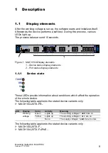
Figure 1: MACH104 Display elements

1 - Device status display elements
2 - Port status display elements

1.1.1

Device state

These LEDs provide information about conditions which affect the operation 
of the whole device.
The following table applies to the stated device variants only:

MACH104-20TX-FR...

The following table applies to the stated device variants only:

MACH104-20TX-F...

MACH104-20TX-F-4PoE...

LED

Display

Color

Activity

Meaning

P

Working 
voltage

Green

Lights up

The working voltages 1 

and

 2 are on.

Yellow

Lights up

The working voltages 1 

or

 2 are on.

None

The supply voltages 1 

and

 2 are too low.

V.24

USB

Aufkleber MAC-Adresse

P

FAULT

FAULT

Sb

RM

5

6

7

8

1

3

2

4

9

11

10

12

13

15

14

16

17

19

18

20

21

23

22

24

MACH104-20TX-F

7

5

1 3

9 11

13 15

17 19

21 23

8

6

2 4

10 12

14 16

18 20

22 24

2

1

FAULT

RM

Sb

P

Summary of Contents for 942003002

Page 1: ...4 20TX F MACH104 20TX FR V 24 USB Aufkleber MAC Adresse P FAULT FAULT Sb RM 5 6 7 8 1 3 2 4 9 11 10 12 13 15 14 16 17 19 18 20 21 23 22 24 MACH104 20TX F V 24 USB Aufkleber MAC Adresse P FAULT FAULT Sb RM 5 6 7 8 1 3 2 4 9 11 10 12 13 15 14 16 17 19 18 20 21 23 22 24 MACH104 20TX FR V 24 USB Aufkleber MAC Adresse P FAULT FAULT Sb RM 5 6 7 8 1 3 2 4 9 11 10 12 13 15 14 16 17 19 18 20 21 23 22 24 MA...

Page 2: ... described here are binding only if they have been expressly agreed when the contract was made This document was produced by Hirschmann Automation and Control GmbH according to the best of the company s knowledge Hirschmann reserves the right to change the contents of this document without prior notice Hirschmann can give no guarantee in respect of the correctness or accuracy of the information in...

Page 3: ...rfaces 10 1 2 1 USB interface 10 2 Installation 11 2 1 Wiring and assembling the signal contact 11 2 2 Installing the device and grounding 12 2 2 1 Selecting the assembly location 12 2 2 2 Mounting on a flat surface 12 2 2 3 Mounting in a switch cabinet 12 2 2 4 Mounting on the wall 13 2 2 5 Grounding the device 13 2 3 Operating the device 14 3 Deinstallation 15 3 1 Removing the device 15 4 Techni...

Page 4: ... are properly trained Training as well as practical knowledge and experience make up their qualifications This is the prerequisite for grounding and labeling circuits devices and systems in accordance with current standards in safety technology Qualified personnel are aware of the dangers that exist in their work Qualified personnel are familiar with appropriate measures against these hazards in o...

Page 5: ... America Only use copper wire conductors of class 1 60 75 C or 75 C Make sure that the disconnecting device is easily accessible so that the MACH104 device can be disconnected from the mains voltage If you disconnect the device from the mains voltage using the plug in the socket an on off switch it must be easily accessible This applies to the following device variants only MACH104 20TX FR Pull bo...

Page 6: ...llowing address Hirschmann Automation and Control GmbH Stuttgarter Str 45 51 72654 Neckartenzlingen Germany Tel 49 1805 141538 The product can be used in the industrial sector Interference immunity EN 61000 6 2 Emitted interference EN 55022 Warning This is a class A device This device can cause interference in living areas and in this case the operator may be required to take appro priate measures...

Page 7: ...onsideration should be given to installing the equipment in an environment compatible with the maximum ambient temperature of the device Reduced Air Flow Installation of the equipment in a rack should be such that the amount of air flow required for safe operation of the equipment is not compromised Mechanical Loading Mounting of the equipment in the rack should be such that a hazardous condition ...

Page 8: ... as PDF files on the CD DVD supplied Installation user manual with additional information on the device Device description Interfaces Configuration EMC and immunity Accessories Basic Configuration user manual Redundancy Configuration user manual Graphical User Interface reference manual Command Line Interface reference manual Legend The symbols used in this manual have the following meanings Listi...

Page 9: ...ditions which affect the operation of the whole device The following table applies to the stated device variants only MACH104 20TX FR The following table applies to the stated device variants only MACH104 20TX F MACH104 20TX F 4PoE LED Display Color Activity Meaning P Working voltage Green Lights up The working voltages 1 and 2 are on Yellow Lights up The working voltages 1 or 2 are on None The su...

Page 10: ...ration and for loading the software LED Display Color Activity Meaning P Working voltage Green Lights up Operating voltage is on None Operating voltage is too low LED Display Color Activity Meaning LS Link status None Device detects an invalid or missing link Green Lights up Device detects a valid link Flashes 1 time a period Port is switched to stand by Flashes 3 times a period Port is switched o...

Page 11: ... on page 16 Remove the power connector from the device Connect the signal contact wires with the connectors of the terminal block Mount the terminal block for the signal contact on the front of the device using the screw locking Check whether the terminal block is mounted correctly and screwed on Note Relevant for North America The torque for tightening the terminal block for the signal contact on...

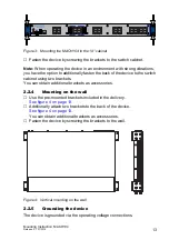
Page 12: ... as a table fasten the housing feet supplied at a distance of 2 cm from the corners of the bottom of the device If necessary remove any dirt from the adhesive surfaces on the bottom of the device Remove the protective foil from the adhesive surface of a housing foot and attach the housing foot 2 2 3 Mounting in a switch cabinet Note Observe the instructions for installation in 19 control cabinets ...

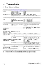
Page 13: ...rackets as accessories 2 2 4 Mounting on the wall Use the pre mounted brackets included in the delivery See figure 4 on page 13 Additionally attach two brackets to the back of the device See figure 4 on page 13 You can obtain additional brackets as accessories Fasten the device by screwing the brackets to the wall Figure 4 Vertical mounting on the wall 2 2 5 Grounding the device The device is grou...

Page 14: ...g voltage on page 5 By connecting the voltage supply via the voltage supply socket s you start the operation of the device WARNING ELECTRIC SHOCK Connect solely an working voltage that corresponds to the type plate of your device Failure to follow these instructions can result in death serious injury or equipment damage ...

Page 15: ...e Disconnect the operating voltage Remove the power connector from the device To detach the device from the switch cabinet or the wall remove the screws from the brackets on the device Figure 5 Disassembling the device V 24 USB Aufkleber MAC Adresse P FAULT FAULT Sb RM 5 6 7 8 1 3 2 4 9 11 10 12 13 15 14 16 17 19 18 20 21 23 22 24 MACH104 20TX F ...

Page 16: ...TX F 4PoE 4 Powered Device PD class 0 15 4 W Power failure bypass 12 ms 115 V AC Overload current protection at input Non replaceable fuse Climatic conditions during operation Ambient air temperaturea a Temperature of the ambient air at a distance of 2 inches 5 cm from the device 32 F 122 F 0 C 50 C Humidity 20 90 non condensing Air pressure minimum 795 hPa 9842 ft 2000 m maximum 1060 hPa 1312 ft ...

Page 17: ...104 20TX F 35 W 119 Btu IT h MACH104 20TX FR 35 W 119 Btu IT h MACH104 20TX F 4PoE when 4 x Class 0 Powered Device connected 110 W 170 Btu IT h Number Article 1 Device 1 2 pin terminal block for signal contact 2 Brackets with fastening screws pre mounted 1 Housing feet stick on mm inch 31 75 1 25 462 6 18 21 43 9 1 73 3 3 0 13 3 3 0 13 4 5 0 18 342 13 46 19 3 0 76 19 3 0 76 444 17 48 ...

Page 18: ... stan dard solely if the approval indicator appears on the housing If your device has a shipping approval according to Germanischer Lloyd you find the approval mark printed on the device label You will find out whether your device has other shipping approvals on the Hirschmann website under www hirschmann com in the product information 1 Non heating appliance cable Euro model 1 Mounting instructio...

Page 19: ...Mounting Instruction MACH104 Release 07 07 2014 19 ...

Page 20: ......

Reviews: