background image

130

RollCall Templates

Row Buttons and Rotary

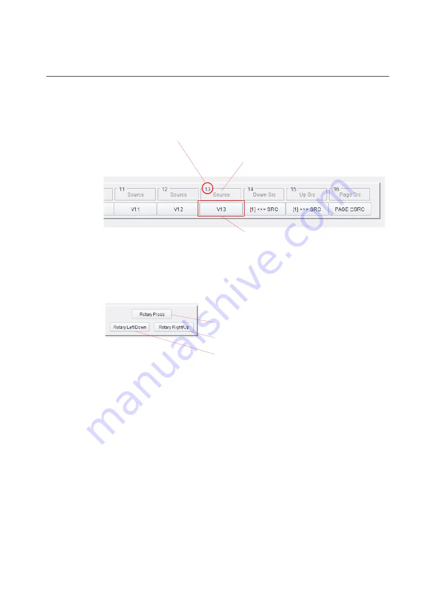
For rotary controls, click a button to mirror pressing the rotary control, turning it clockwise 
and counter-clockwise. See Figure 5-54.

Fig. 5-53: Button Representation

Fig. 5-54: Rotary Control Representation (LCD panel only)

For example:

• To Lock / Unlock the panel from the template:

Click the ‘Lock’ soft button.

Click again to unlock.

• To make a route from the template:

Select a destination.

Select a source via the soft buttons.

Then click the ‘Take’ soft button.

Button function

Button number in the button row 

Note:


This is NOT a source port nor 
destination port number.

Soft button, 

annotated to reflect the physical button

Press to perform same action as:

• Pressing rotary control.

• Rotate control to the right, increasing in value.

• Rotate control to the left, decreasing in value.

Summary of Contents for 1RU32LCD-BK-K

Page 1: ...G2 SERIES 1U ROUTER CONTROL PANEL SHALLOW 40 LED BUTTON AND 32 LCD BUTTON VERSIONS User Manual Issue 1 Revision 2 2020 05 18...

Page 2: ...r Control Panel documentation you agree to the following terms and conditions Grass Valley hereby grants permission and license to owners of G2 Series 1U Router Control Panels to use their product man...

Page 3: ...iii G2 Series 1U Router Control Panel User Manual Safety Information...

Page 4: ...iv Notices...

Page 5: ...v G2 Series 1U Router Control Panel User Manual...

Page 6: ...ive grounding terminal which must be connected to earth ground prior to making any other equipment connections Identifies an external protective grounding terminal which may be connected to earth grou...

Page 7: ...cleaning the equipment Do not use liquid or aerosol cleaners use only a damp cloth Dangerous voltages may exist at several points in this equipment To avoid injury do not touch exposed connections an...

Page 8: ...ervicing should be done in a static free environment To reduce the risk of electric shock plug each power supply cord into separate branch circuits employing separate service grounds This unit may hav...

Page 9: ...equipment must be carried out by persons qualified to work with equipment which may be connected to a mains electric supply CAUTION RISK OF ELECTRIC SHOCK DO NOT REMOVE COVERS NO USER SERVICABLE PART...

Page 10: ...gether with its separate external power supply module s must be supplied from a power supply system providing a PROTECTIVE EARTH connection and having a neutral connection which can be reliably identi...

Page 11: ...00 3 2 2014 Class A Limits for harmonic current emissions EN 61000 3 3 2013 Limitation of voltage changes voltage fluctuations and flicker in public low voltage supply systems EN 55103 2 2009 Environm...

Page 12: ...gnated Network Environment 0 as defined in IEC TR 62102 In accordance with EN 60950 1 the Ethernet port is classified as SELV Low voltage Serviceable Items There are no serviceable items within the G2...

Page 13: ...roduct Overview 1 2 Hardware Description 13 3 Hardware Installation 29 4 Web Page 35 5 RollCall Templates 37 6 Getting Started 159 7 Operation 195 8 Maintenance 225 Appendix A Technical Specification...

Page 14: ...xiv Table of Contents...

Page 15: ...EMC Environment xii EMC Performance of Cables and Connectors xii Serviceable Items xii Recycling xii Top Level Contents List xiii Full Table of Contents xv 1 Product Overview 1 Order Codes 2 Unit Func...

Page 16: ...ED Button Labeling 29 Button Arrangement 29 Label Inserts 30 Prepare Label Inserts 30 Fit Label Inserts 30 Rack Mounting 32 Connections 33 Power On Sequence 34 Power Off 34 4 Web Page 35 Web Page 35 5...

Page 17: ...on 83 Page View Control Indicator 84 Source Page Configuration Pane 84 Destination Page Configuration Pane 85 Source Destination Page Configuration 87 Page Operations 94 Other Panes and Controls 97 LC...

Page 18: ...tings 166 Default Source Destination Assignments 167 Panel XY Mode 167 Panel BPX Mode 167 Panel Group Mode 167 Button Example 1 XY Panel Mode LCD Panel 168 Mapping XY Buttons LCD Panel 168 Preliminari...

Page 19: ...ination to BPX Buttons 181 Preliminaries 181 Assign BPX Crosspoint Pages 181 In the BPX Mapping template to assign for page 1 181 Crosspoint Page 2 181 Crosspoint Pages 3 to 10 182 Buttons Example 5 G...

Page 20: ...210 Protect a Destination BPX 211 Unprotect a Destination BPX 211 Group Mode Panel Operation 212 Group Mode Source Destination Page Navigation 212 Using the Rotary Control 212 Group Mode Button Examp...

Page 21: ...or 236 Ethernet Connector 236 Push Buttons 237 LED Push Buttons 237 LCD Push Buttons 237 Defaults 238 Default IP Settings 238 Default RollCall Settings 238 DC Power Supply Module 239 Appendix B LED Bu...

Page 22: ...xxii Table of Contents...

Page 23: ...trol panel for router control It is compatible with current Grass Valley routers and router controllers which support the RollCall protocol including IP routing controllers These control panels are av...

Page 24: ...ear Ethernet connection dual redundant power supply connection Configurable operation button layout and button function Fig 1 3 LCD Button Panel Order code 1RU32LCD BK K Order Codes Tab 1 1 G2 Series...

Page 25: ...ually select a destination and a source BPX panel single button press to make a route Destination and source are selected together Additionally an LCD panel has a Group operational mode Group mode has...

Page 26: ...ontrollers and annotates LCD buttons Overall unit functionality is governed by the version of software running on the unit Router control panels use specific router control software which drives the p...

Page 27: ...Button Arrangements b Further Example Arrangements 12 Source selection buttons 12 Destination selection buttons Unassigned buttons Source page selection buttons Destination page selection buttons Take...

Page 28: ...ither fixed text or text according to the operational button selections made LED panels can have fixed labels fitted to LED buttons to identify buttons and button function accordingly in operation All...

Page 29: ...ce the required source and destination s are selected the route may be made Basic Route Making The basic function of the control panel is to select router destinations and sources and make routes on a...

Page 30: ...en selected When the route is made Taken a source signal is routed to a selected destination as shown in Figure 1 8d This Take step can be optionally carried out with a single button press Take button...

Page 31: ...ng particular destination s and source s This can be difficult on a small panel with a larger sized router and many sources and destinations To help the specifying of the ports may be done by Router p...

Page 32: ...and Custom Group sub modes are available Dial Up This mode is useful when port numbers are known Operation Select destination and source by dialing in router port numbers on numeric keys ABC This mode...

Page 33: ...er defined categories with alpha numeric keys Navigation follows the user defined categories down to the target port name Group mode LCD panel only enables user definable source and destination catego...

Page 34: ...label a button with what it does For example Take and Undo Panel button types Fixed Buttons with a fixed function for example Take Dynamic Buttons that change their function according to panel state...

Page 35: ...packed separately One Power Supply Module AC mains cord If there is anything incorrect notify your Grass Valley Partner or Grass Valley at once Grass Valley Technical Support on page 247 2 Check that...

Page 36: ...t connector The control panel has a dual redundant power supply arrangement with two external power supply modules which supply DC power from AC main supplies The control panel chassis is has no force...

Page 37: ...separate This enables the fitting of identifying button labels within the key cap A key cap for an LED button comprises A clear cover A white square insert There are 40 off clear covers and 40 off whi...

Page 38: ...rols may be configured for router control LED Push Buttons These buttons are typically user configured to illuminate in various colors during panel operation LCD Push Buttons These buttons are typical...

Page 39: ...n source pages and destination pages Panel Reset A panel reset re starts the panel It can be carried out from the front panel by pressing three controls at the same time for more than 3 seconds see Fi...

Page 40: ...tart it temporarily displays panel IP Address and Subnet mask see Figure 2 5a and b Fig 2 5 IP Address Information on Buttons a LCD Panel b LED Panel While the panel is operational IP address informat...

Page 41: ...state after approximately 5 seconds Press any three adjacent buttons in a row to see IP address information on LCD buttons IP address shown across left hand side button faces for example First router...

Page 42: ...in for 5 seconds and release to carry out a first level factory reset on the control panel Full factory reset Long push Push the button in for more than 15 seconds to carry out a full factory reset o...

Page 43: ...Power Inlets DC power supply connections Each inlet has a threaded outer casing Each inlet is rated 12V DC 2A max See Section DC Power Inlets on page 23 for more information See Note1 PSU1 The unit c...

Page 44: ...network port auto negotiates connection speed and has automatic cross over Fig 2 8 Rear Ethernet Connector Tab 2 3 Ethernet LEDs Ethernet Link LEDs Description Upper LED Lower LED Off Off No network c...

Page 45: ...each module connected to a separate AC mains supply One DC power connection can be disconnected or connected from the unit while the unit is operating Fuses The G2 Series 1U Router Control Panel does...

Page 46: ...t hand LCD button show panel IP address and subnet mask 4 LCD Left hand LCD buttons show an information display Panel IP address router controller IP address Panel software version and Panel ID inform...

Page 47: ...of operations is similar for an LCD or an LED panel In the description below an LCD panel is shown 1 Using a suitable tool press on the Factory Reset rear recessed push button and continue to press it...

Page 48: ...ntinue to press it The upper row of buttons in the block of 32 LCD or 40 LED front panel push buttons illuminate red one by one from left to right An LCD button lower right on an LCD panel upper right...

Page 49: ...0 Overall the button is pressed for approximately 15 seconds A full factory reset is carried out 5 The panel re boots and the lower right LCD button displays RE BOOT 6 A panel start up sequence is the...

Page 50: ...28 Hardware Description Full Factory Reset...

Page 51: ...ps separate and not fitted Clear film labels not supplied may be added into each key cap before fitting to each button Thus the LED buttons can be labeled For the LED panel LED button key caps need to...

Page 52: ...Inserts 1 Prepare square label inserts for each button on clear film See appendix LED Button Label Templates on page 241 for some square label insert templates Fit Label Inserts To fit label inserts...

Page 53: ...button key caps can be removed again but this is a delicate operation Ensure correct labeling CAUTION An LCD button key cap is NOT removable The single LCD button onLED panels is fully assembled and...

Page 54: ...rack system or desk When the panel is in position use four M6 screws and washers to fasten it to the rack brackets see Figure 3 3 Fig 3 3 Typical Rack Mounting LED panel version shown Allow 80mm appro...

Page 55: ...plug onto each rear DC power inlet by screwing and tightening the threaded ring on the DC power jack plug Dual redundancy is available by using both rear DC power connectors and two separate power sou...

Page 56: ...panel connects to a router controller to gather information 4 Pushbuttons assigned their operational router control functions and button face text 5 If there is no communications link to a router con...

Page 57: ...r displays a web page when it accesses the G2 Series 1U Router Control Panel s IP address See Appendix A Technical Specification on page 233 for default IP address information Fig 4 1 Web Page LCD Pan...

Page 58: ...ateway Gateway IP address for the control panel Panel name RollCall unit name Save Button Click to locally save new settings entered on the web page System information Text boxes for basic panel statu...

Page 59: ...ge 53 Config Template page 55 XY Mapping Template page 72 BPX Mapping Template page 100 Group Mapping Template page 120 XY Status Control Template page 128 BPX Status Control Template page 131 Level C...

Page 60: ...plates vary slightly depending on the panel mode This is highlighted in the template descriptions in this chapter Any RollCall template differences between LCD panels and LED panels are also highlight...

Page 61: ...nfigured button and operate the panel from the template BPX Status Control Template on page 131 view the status of each configured button and control the panel using the on screen buttons which work a...

Page 62: ...box located at the top of each G2 Series 1U Router Control Panel template Fig 5 2 Template Selection Box Right Click Right click in a template to see a pop up list of all the control panel s templates...

Page 63: ...setting Setting Values with a Slider Fig 5 4 Template Slider Many of the settings within the templates are numerical and can be set with a slider bar on the template To set such numerical values Click...

Page 64: ...splays some system status and allows setting of panel IP address settings from the template Fig 5 5 System Template Connection status information box appears on each template see Table 5 1 Ethernet Co...

Page 65: ...e current name in the field Enter the new unit name Press S or press the Enter key to locally save a new name Restart Button Click Restart to restart the panel and apply settings changes made in the t...

Page 66: ...ey or click S See Note 1 Save Changes Button Click to locally save changes made Note Changes only take effect after a restart IP Address IP address of control panel Subnet address Subnet used by contr...

Page 67: ...the controller s Fig 5 6 Setup Template See Router Connection on page 50 See Table 5 4 See Table 5 5 See Table 5 6 Tab 5 4 Setup Template Profile Config Items Profile Config Pane Item Description Pro...

Page 68: ...le Tab 5 5 Setup Template Panel Mode Items Panel Mode Item Description Panel Mode Check boxes Select panel mode of operation for router control Some RollCall templates depend upon which panel mode is...

Page 69: ...which is loaded into the panel Note The xml file is defined and works in a similar way to a Grass Valley KKT panel A Grass Valley Router Control Panel Configurator tool is used which is based on Micr...

Page 70: ...ation Router controller IP configuration settings are not altered when resetting the panel to the factory default settings The current panel operating mode is unaffected by pressing this button Factor...

Page 71: ...flash thus indicating the panel s position For example when there are a number of control panels in a system in use or configured panels may be identified Enable Check box Select to flash all panel b...

Page 72: ...ormation Note If this information is being sourced from a panel configuration profile from a downloaded XML file then these fields are grayed out IP Address Enter new IP address of the router controll...

Page 73: ...tting is the same for both controllers for a dual controller system See Note 1 Note 2 and Note 3 below Connection Status Displays the status of the panel s connection to the router controller s Values...

Page 74: ...Note 1 When configuring a router using a 24xx controller the default RC network address 0000 81 00 is automatically set Note 2 On a router with a 24xx controller the default RC Network address relates...

Page 75: ...rofile configuration files in XML format The files are defined in the same way as Grass Valley KKT panels See 6026KKT RC Series 2U Control Panels User Manual Router Controller Configurator section for...

Page 76: ...ion Name Name of the router connection in the panel profile TCP Port TCP port number used by router controller connections Long Names 8 or 32 character names setting Protect Device ID Panel profile de...

Page 77: ...0 and Figure 5 11 The template is used for setting up fixed button options and the text format that displays on LCD buttons on LCD panels Fig 5 9 Config Template LCD Panel XY Panel Mode BPX Mode Note...

Page 78: ...56 RollCall Templates Config Template Fig 5 10 Config Template LED Panel XY or BPX Mode Fig 5 11 Config Template LCD Panel Group Mode For LED panel XY or BPX mode For LCD panel Group mode...

Page 79: ...age 59 Locate the descriptions of each template pane by clicking on a link Protect Flash and Timeouts Pane on page 62 Fixed Button Text Pane on page 67 Search Options Pane on page 65 Destination Sourc...

Page 80: ...ton In BPX mode a single button press selects a destination and a source for routing with an optional Take Group Radio button LCD panel only Panel operating mode where destination source pairs and gro...

Page 81: ...ton must still be assigned on the panel with the corresponding Mapping template A Take button then becomes active when a new route is selected Pressing Take then makes the new route Note 2 If deselect...

Page 82: ...Timeout Slider Set the Take timeout value seconds Press P for the default of 6 seconds When the value is set to OFF the status is shown until the next route is made Undo Timer Displays the duration af...

Page 83: ...anel after a route has been taken if Undo is enabled and if there is an undo button type on the panel For example after a Take 1 A Take Undo button temporarily changes color and is renamed Undo for th...

Page 84: ...outed select the unprotected destination and press Protect To remove a Protect on a destination select the protected destination and press Protect LED panel To protect a destination from being routed...

Page 85: ...Certain buttons flash in a particular state Connection Loss Check box Select to flash all buttons on loss of the corresponding source or destination connection at the router New Source Check box Sele...

Page 86: ...s Dim Timeout is the period of button inactivity after which a panel dims its LCD buttons Slider Select LCD Brightness Dim Timeout value Press P to set default of 5 minutes Power Up Connect Delay Powe...

Page 87: ...select a port item if it is the only item resulting from a search through the customs groups I e There is no need to press the source button itself if only one source item remains in the search Group...

Page 88: ...ection box Determines port list order shown on destination or source buttons in panel group mode This controls the list order of ports and hence what is shown when paging through all sources or a filt...

Page 89: ...ndo Protect Locked State and Unlocked State These buttons may each contain up to three lines of text each line contains up to six characters each line must be delimited by a space character For exampl...

Page 90: ...LCD XY Dest BPX Text Format Pane This pane defines the button face text format on LCD buttons for Destination buttons in XY panel mode Source Destination buttons in BPX panel mode Select the radio but...

Page 91: ...ng Text Dest Port Source Port 8 character names only Medium Text Dest Port 7 chars max Medium Text 7 chars max Custom See Custom Text Long Text LCD Display Preferences Pane on page 71 Note When a dest...

Page 92: ...n face text format Fig 5 19 LCD Source Text Format Pane XY Panel Mode Only Tab 5 16 LCD Source Text Format Options Text Format Option XY Source button face example Long Text Split Text Long Text Port...

Page 93: ...button face text format preferences on LCD buttons Long up to 32 character source and destination names are supported by the panels The controls in this pane are used to manipulate the names to suit...

Page 94: ...available in a flexible manner The user can Define button function types for each dynamic source and destination button Define the number of and the means of accessing each page of source or destinati...

Page 95: ...mapping of the buttons defines what displays on each button when the source and destinations are setup in their respective pages and how the individual pages are to be accessed Figure 5 23 and Figure...

Page 96: ...74 RollCall Templates XY Mapping Template Fig 5 24 XY Mapping Template LCD Panel Right hand side...

Page 97: ...Areas panes of the template are described in sub sections and Figure 5 25 shows this Locate a pane s description by clicking on the link contained in the figure Fig 5 25 XY Mapping Template Panes Pan...

Page 98: ...is described in Source and Destination Page Configuration on page 83 Fig 5 26 Panel Button Map LCD panel shown Buttons are configured individually They are selectable with navigation controls in the...

Page 99: ...on controls to move the button focus and select any button on the Panel Button Map This selects which panel button to define Slider Use the slider to select and focus on a button in the button map Whe...

Page 100: ...ype Controls for configuring the button function type of several source or destination selection buttons Note This fill control sets the type of function that a button carries out It does not assign s...

Page 101: ...ck to autofill Button Type to panel buttons from the button focus position Buttons will be assigned and labeled according to the autofill button type and the number of buttons Other button types may b...

Page 102: ...0 RollCall Templates Button Configuration Pane Fig 5 28 Panel Button Map Focus Fig 5 29 Button Autofill Patterns a Across b Up Down Across Selected button focus on this button a Across b Up Down Acros...

Page 103: ...lity Undo Only Defines a button with route Undo functionality Status Define a LCD text button to display the status of routes that are made Status reported includes a successful route a failed route t...

Page 104: ...l page of destinations Page Src Up Defines a single button to navigate forwards through pages of sources When on the last page pressing this button navigates to the first page Page Src Down Defines a...

Page 105: ...en configuring a destination button function the Destination Page Configuration pane is shown See Figure 5 31 and Figure 5 33 In both cases some page view controls indicators are shown at the bottom o...

Page 106: ...View Items Item Description Current Selected Text fields This appears in a slightly different position on the template for LCD panels and for LED panels Display the currently selected source and desti...

Page 107: ...s 1U Router Control Panel User Manual Fig 5 32 Source Page Configuration Pane Destination Page Configuration Pane An example Destination Page Configuration pane is shown in Figure 5 33 Source Assignme...

Page 108: ...86 RollCall Templates Source and Destination Page Configuration Fig 5 33 Destination Page configuration Pane Destination Assignment list box...

Page 109: ...nction types must be defined before setting up the source and destination pages See Button Configuration Pane on page 77 Tab 5 20 Source Destination Page Configuration Items Item Description Index Foc...

Page 110: ...rent page Change the Page in View value Change the page on the control panel unit Note If page navigation buttons have been previously configured on the panel these can be used to navigate through the...

Page 111: ...selected button on the current page Note These controls are not annotated on the template Source Destination Port List box Select the source or destination port name to assign to the selected button...

Page 112: ...ce Destination Port list box Enter a value in the text box and press the Enter key Press P to set to zero 500 Buttons Click to Increment decrement Index value 100 500 100 Listbox Filter Text box Enter...

Page 113: ...yields the following button face text Copy Page Name Button Click to insert the page name into the text box If the page has not been named then the page number is inserted For example 2 Text may be a...

Page 114: ...to be assigned later Fill from Last Assigned Button Similar to Fill but continuing on from the last assigned port 1 1 Fill from Last Assigned Button Similar to 1 1 Fill but continuing on from the las...

Page 115: ...erations Page Operations Pages can be added removed copied or the order of pages changed at any time using the Page Operations features Drop down box Select the page operation required See Page Operat...

Page 116: ...age button Source or destinations assigned to buttons on the current page are unassigned The template shows the assigned source or destination as Unused RemovePage Removes the current page Note Perfor...

Page 117: ...age Move the current page The current page is moved to the page number defined on the Copy To Move To Page slider target page Note This will replace the target page The current page is then set to a b...

Page 118: ...st page will be lost and removed To insert a blank page before the current page Go to a page on the XY Mapping template If the last page is to be kept increase the Number of Pages Select Insert BlankP...

Page 119: ...tomatically fill the panel buttons with a default configuration on power up Caution This over rides all page settings Note As soon as any changes are made to the configuration the LCD XY Setup state c...

Page 120: ...t 1 to 10 text box 2 Move the button focus to the button to which the text is to be added 3 In the Button Type drop down list Figure 5 36 in the Button Configuration Pane on page 77 select Text N wher...

Page 121: ...selected Select check box source page displayed changes to show the page containing the currently routed source routed to the selected destination Deselect check box source page displayed is unaffect...

Page 122: ...ber of and the means of accessing each page of crosspoint selection buttons Allocate specific crosspoints to individual buttons on each page It may be useful to group certain crosspoints together on a...

Page 123: ...mapping of the buttons defines what displays on each button when the crosspoints are setup in their respective pages and how the individual pages are to be accessed Figure 5 38 and Figure 5 31 show th...

Page 124: ...102 RollCall Templates BPX Mapping Template Fig 5 39 BPX Mapping Template LCD Panel Right hand side...

Page 125: ...ndicators Areas panes of the template are described in sub sections and Figure 5 40 shows this Locate a pane s description by clicking on the link contained in the figure Fig 5 40 BPX Mapping Template...

Page 126: ...esented and annotated according to its function on the crosspoint page currently selected These are shown in Figure 5 41 and Figure 5 42 for and LCD panel and LED panel respectively Fig 5 41 BPX Panel...

Page 127: ...le shown Buttons are configured individually They are selectable with navigation controls in the template s Button Configuration section See BPX Button Page Controls and General Controls on page 106 P...

Page 128: ...r enter value in the text box and press the Enter key Page In View Slider and text box The Page in View is the page viewed on the template and on the control panel unit too To change Page in View use...

Page 129: ...dditionally show port numbers in various controls on this template BPX Single Destination Options Single BPX Dest for all pages Check box Select to apply one destination across all pages This assists...

Page 130: ...Button Page Controls and General Controls Destinations Drop down box Select the name to use for showing destinations in the template controls Level names Association names Tab 5 26 General Controls c...

Page 131: ...op down list box see Button Function Type BPX on page 111 Button Focus see Button Focus on page 109 BPX Destination see BPX Destination Assignment on page 113 BPX Source see BPX Source Assignment on p...

Page 132: ...3 buttons 1 Click to move button focus leftwards by 1 button Row Click to toggle button row 1 Click to move button focus rightwards by 1 button 3 Click to move button focus rightwards by 3 buttons De...

Page 133: ...utton focus See Table 5 29 BPX Button FunctionTypes on page 111 for a description of each button function type Tab 5 29 BPX Button Function Types Button Function type Description Unassigned Sets the c...

Page 134: ...is button navigates to the last page Paging LCD panel Defines a button as a Page Button for accessing crosspoint pages When the pressed it displays all pages allowing direct selection of an individual...

Page 135: ...tination drop down listbox Select destination for selected button Select the destination from the drop down list The list contains up to 100 port names The destination name or name and number are list...

Page 136: ...router controller salvos Destination Listbox Filter Text box Enter text and press S or press the Enter key Press P to set default Dest The text is used to filter the contents of the destination list...

Page 137: ...s assigned the same destination Note 1 A Destination must be assigned to buttons for this auto increment to work Note 2 If a button has been assigned to anything other than BPX then the incrementing s...

Page 138: ...schemes may be customized see LED Colors BPX Template on page 145 for LED color schemes Text Text box Enter text to appear as label text on the button then press S or press the Enter key Press P to c...

Page 139: ...on Map Focus Tab 5 34 BPX Button Fill Controls Item Description Increment Type Selection box Select the increment direction pattern to fill the BPX buttons Up Down Across Across AutoFill Number to Fil...

Page 140: ...ination Source Fill buttons with the current button focus s source Source increment Fill buttons with an incrementing source port number starting from the current button focus s source Colour A B C or...

Page 141: ...47 BPX Button Filling Examples a BPX Unassigned 8 buttons filled as Unassigned BPX buttons b Current Dest All destinations set to V15 c Source All sources set to V1 d Source increment Sources filed ou...

Page 142: ...igure 5 49 Fig 5 49 Areas of the Group Mapping Template Note Ensure that the target router has been configured with all the desired port names before starting the button mapping process Buttons 1 to 6...

Page 143: ...ons which work as if pressing the actual panel buttons and rotary control This is similar to the XY Status Control and BPX Status Control RollCall templates for XY and BPX panel modes respectively Fig...

Page 144: ...ms Item Description Button configuration Drop down box Select the button function type See Button Function Type Group on page 124 Template button Button on the template which allows the user to view t...

Page 145: ...w Preset Dest on Top Button Click to arrange destination controls on the top button row of the panel And source controls on bottom row Keypad Format Radio buttons Set the number format of the numeric...

Page 146: ...ction Types Button Type Description Unassigned Sets the current button to be blank and have no function Group Define a button to show available user defined categories custom groups See Note 1 Active...

Page 147: ...r the panel buttons Text Defines a LCD text button as text button which displays text Port Select Define a button to cycle between the following panel Group sub modes GRP Custom Group mode user define...

Page 148: ...o control routing to a router s monitor ports Lock Unlock Defines a Panel Lock Unlock button Protect Defines a button with destination protect functionality Level Defines a button to select router lev...

Page 149: ...estination type buttons are placed on a panel These show the sources destinations filtered by the group selection buttons When there are more sources destinations than buttons one of the buttons in th...

Page 150: ...is available for both LCD and LED panels in panel XY mode It allows the user to View the status of each configured button Operate the panel from the template using the template s on screen buttons wh...

Page 151: ...rror the action of pressing the same physical button on the control panel unit itself See Figure 5 53 a XY Status Control Template Zoomed out Overview b XY Status Control Template Zoomed in view LCD p...

Page 152: ...rom the template Click the Lock soft button Click again to unlock To make a route from the template Select a destination Select a source via the soft buttons Then click the Take soft button Button fun...

Page 153: ...te is similar for LCD and LED panels Only the panel button map differs reflecting the different button layouts on each panel type Fig 5 55 BPX Status Control Template a Zoomed out overview b Zoomed in...

Page 154: ...nter clockwise See Figure 5 57 Fig 5 56 Button Representation Fig 5 57 Rotary Control Representation LCD panel only For example To Lock Unlock the panel from the template Click the Lock soft button Cl...

Page 155: ...to select it and then to change the button focus value drag the slider or use the left right arrows keys Or Click on the button focus value and enter a value and then press the Enter key Button Text...

Page 156: ...hest Level Shows the highest Level currently operating in the system Levels Active on Button For a Level configuration configure which router levels shall be active LEVEL 1 LEVEL 2 Each router level i...

Page 157: ...re independent of the normal router destinations Monitor ports can monitor signals derived directly or indirectly from router sources or destinations router dependent This template is used to determin...

Page 158: ...ut signal following any input audio processing for video AHP router modules only Output Type Radio buttons to select which router output signal type to monitor Pre Processing Select to monitor a route...

Page 159: ...monitor signal derived from the selected source destination is presented at the monitor port 3 The panel will route any subsequently selected source or selected destination to the monitor port For ex...

Page 160: ...ns that appear on the panel from left to right top to bottom Fig 5 60 TAKE Configuration Template Note The ability to configure levels and tracks depends on the router controller and the connected rou...

Page 161: ...e text box and press S or press the Enter key TAKE Settings TAKE Index Slider Select the TAKE button to configure in this pane Display Text Text box Enter text to display on the button face and press...

Page 162: ...140 RollCall Templates TAKE Configuration Template Fig 5 62 Routing Type and TAKE Settings a Association Levels b Track Routing a Association Levels settings b Track Routing settings...

Page 163: ...e initiated from the control panel Use Panel Salvos to return a router back to a known state or to an alternative starting point with different settings Up to 64 Panel Salvos can be defined Salvo IDs...

Page 164: ...OK Active Salvo is active All configured salvo routes are true tallied WARN Some parameters in the salvo are incorrect or incomplete FAIL Salvo is not accessible This usually indicates a duplicate des...

Page 165: ...nd Destination selection sliders XY 1 Route definition Tab 5 44 Panel Salvo Route Definition Items Item Description XY 1 to XY 30 Up to 30 routes can be made by a panel salvo Define each route XY 1 up...

Page 166: ...essages and all higher levels This is set to Information by default The control panel can log messages to a log server in syslog format which have severity level attributes Syslog severity level optio...

Page 167: ...for the different BPX color schemes allowing grouping of buttons Fig 5 67 LED Colors BPX Template Tab 5 46 LED Colors BPX Template Items Control Item Description Default All Colors Button Click to set...

Page 168: ...n Tab 5 47 Customizable LED Colors BPX Button State Button Color Description BPX A Unselected Color scheme A for unselected BPX buttons BPX A Selected Color scheme A for selected BPX buttons BPX B Uns...

Page 169: ...suit their application or to suit user preferences LED color customizing is done in the same way for LED panels or LCD panels i e it applies to both LED or LCD buttons Colors are set for various butto...

Page 170: ...n Red Green Blue Slider Slider per color component value Defines the button color with separate sliders for red green and blue Range 0 to 255 To change the color component value with the slider Click...

Page 171: ...destination is protected Routed Source Source currently routed to the selected destination Text Buttons Color for buttons assigned to display free text Unmarried Selected Destination Selected destinat...

Page 172: ...in Figure 5 69 Buttons on the panel have colors that can be customized to suit their application or to suit user preferences Color customizing is done in the same way for LED or LCD panels The templat...

Page 173: ...the color component value with the slider Click on a slider to select it then either drag the slider to change the color component value or use left right arrow keys to increment decrement the value...

Page 174: ...normal color Take Available Take button when a destination and new source have been selected Text Unavailable Take button when a Take function is not available in the current panel state e g before a...

Page 175: ...panel have colors that can be customized to suit their application or to suit user preferences The template defines the back light color for buttons in panel Group mode Fig 5 70 LED Colors Group Keys...

Page 176: ...Keys Button State Button Color Description Source Available Main source selection color Used on group selection buttons This shows that a source is available Source Unavailable Source selection color...

Page 177: ...utton Includes group keys Port Select Port Select button color Control Color of control type panel buttons that navigate the panel buttons For example the Back button or the SEL Toggle button Matrix C...

Page 178: ...k in the text box type in a new address and press S or press the Enter key Secondary Connection Text box The Secondary IP Address of the remote RollNet IP Share unit Bridge IP Port Text box The IP por...

Page 179: ...the IP Bridge Tab 5 55 RollCall IP Bridging Status Items Status Item Description Remote IP Address Displays the IP address of the remote end of the IP Bridge when connected Started By Shows the initia...

Page 180: ...158 RollCall Templates IP Bridging Template...

Page 181: ...lates page 165 Default Source Destination Assignments page 167 Button Example 1 XY Panel Mode LCD Panel page 168 Button Example 2 XY Panel Mode LED Panel page 173 Button Example 3 BPX Panel Mode LCD P...

Page 182: ...n its network port To set up the control panel s IP address etc 1 Set a PC Ethernet port to be on the same IP subnet as the panel Give the port an IP address in the same range as the panel and assign...

Page 183: ...ss Subnet mask Gateway IP address and also Panel name 6 Click the Save button on the web page 7 Click Apply and Restart on the web page The panel restarts and the new IP settings are applied 8 Verify...

Page 184: ...Series 1U Router Control Panel 1 On the computer open the RollCall Control Panel application On Windows 7 Start All Programs SAM RollCall Control Panel The RollCall Control Panel application starts an...

Page 185: ...ing Connecting the RollCall application connects to the G2 Series 1U Router Control Panel unit The unit is shown on the left of the screen 4 To connect to the unit and open templates Double click on t...

Page 186: ...164 Getting Started Connect RollCall Control Panel Fig 6 4 RollCall Control Panel Connected RollCall Control Panel software has now connected to the unit G2 Series 1U Router Control Panel...

Page 187: ...IP address of the router to connect to into the Primary pane s IP address field and press the Enter key or click S 3 Enter the RollCall address RC Network address of the router controller Typically t...

Page 188: ...outer Connection Status Panel Reset See Hardware Description on page 13 Restoring Factory Settings See Hardware Description on page 13 Note If the status does not display as Connected Active after ini...

Page 189: ...l sources and destinations on the panel The full size of the router is used This is shown on the RollCall Setup template Router Dimensions X Y Router Sources and Router Dests Source and destination na...

Page 190: ...osition the Button Focus at the top left panel button row 1 button 1 4 Set a Button Configuration to XY Source in the drop down list b Number to Fill to 12 Press S c Increment Type to Across d Autofil...

Page 191: ...pe to Destination in the selection box 19 Click Fill The first 12 buttons of row 2 display with Destination N or Destination Unused in the button map These are now assigned with a destination selectio...

Page 192: ...tons LCD Panel on page 168 It assigns source ports to the mapped source selection buttons Source Page1 In the XY Mapping template s Source Page Configuration section configure source buttons for the f...

Page 193: ...ned for each source page Assign Ports to XY Destination Pages This section continues on from Assign Ports to XY Source Pages on page 170 It assigns destination ports to the mapped destination selectio...

Page 194: ...buttons are populated with destinations according to the numerical order of the port numbers continuing from last port number on the previous page 8 Repeat the above sequence for subsequent required p...

Page 195: ...ed Status Timeout to 4seconds d Set Undo Timeout to 4 seconds Map Top Row XY Buttons Source Selection In the XY Mapping template 3 Position the Button Focus at the top left panel button row 1 button 1...

Page 196: ...tioned at the next 19th button on the row Map Bottom Row Other Buttons 20 Set Button Configuration to Protect 21 Increment Button Focus click 1 to move to the next button 22 Set Button Configuration t...

Page 197: ...ws source page 1 4 Position Index Focus at row 1 button 1 Source buttons are filled in from this point forwards within the confines of the source current page 5 In AutoFill set Start Port to 1 6 In Au...

Page 198: ...s the source and the destination on the LCD button Mapping Button Functions Use the BPX Mapping template Map Top Row BPX Buttons 1 Position the Button Focus at the top left panel button button map row...

Page 199: ...V10 8 Set Source to V1 9 Set Type to Source increment 10 Click Fill The first 8 LCD buttons are assigned sources V1 to V8 11 Set Type to Colour A 12 Click Fill The first 8 LCD buttons have their butto...

Page 200: ...to Colour C This has made assignments to the next block of 8 BPX buttons 26 Repeat steps in Set Next 8 BPX Buttons on page 177 with the following changed settings Position the Button Focus at the top...

Page 201: ...n Focus on the top left button of the panel button map row 1 button 1 2 Set Button Type to BPX in the drop down list 3 Set Number to Fill to 12 Press S 4 Set Increment Type to Across 5 Click Fill The...

Page 202: ...election function Now proceed to the remaining bottom row buttons Map Fixed function BPX Buttons 23 Set Button Focus at the 13th button on the row row 2 button1 24 Select Button Type to be Global Text...

Page 203: ...int page 1 In the Button Configuration section to configure BPX buttons for the first page of crosspoints 4 Set Button Focus at the first BPX button row 1 button 1 BPX buttons will be filled in from t...

Page 204: ...Focus at row 1 button 1 BPX buttons will be filled in from this point forwards for crosspoint page 2 17 Set Destination to VN the next item in the Destination drop down list 18 Set Source to V1 the fi...

Page 205: ...XY Mode Take Enable b Select XY Mode Undo Enable c Set Routed Status Timeout to 4 seconds d Set Undo Timeout to 4 seconds 3 In the Search Options pane a Select Auto Select Single Filtered Port b Setec...

Page 206: ...ttons 17 to 18 in Rows 1 and 2 4 Select each button function type with the corresponding drop down selection box and set button types to those shown in Figure 6 15 Fig 6 15 Map Buttons 17 to 18 Result...

Page 207: ...how Selected Group Back Group sub mode select Group select Dial ABC Destination mode Toggle Source Destination mode Show routed source Dial Up buttons 5x2 Note If more Source Selection or Destination...

Page 208: ...he G2 Series 1U Router Control Panel may be saved with the RollCall Control Panel application This is useful if a number of user configurations are required for different tasks or for copying a config...

Page 209: ...selected folder a dialog box is shown asking if the file can be overwritten Click Save Saving begins Fig 6 19 Saving 5 Click OK when saving is complete Fig 6 20 Save Complete Note When connected dire...

Page 210: ...all Control Panel to the G2 Series 1U Router Control Panel 2 Right click on the router control panel s unit name and click Restore in the pop up menu See Figure 6 21 A Restore Setup for dialog is show...

Page 211: ...ore begins Fig 6 24 Restoring 7 Click OK when restoring is complete Fig 6 25 Restore Complete Note The restore can take several minutes The control panel cannot be used while the restore is in progres...

Page 212: ...for the button See Button Function Type XY on page 81 or see Button Function Type BPX on page 111 or see Button Function Type Group on page 124 This has re assigned the button function on the G2 Serie...

Page 213: ...can have text displayed on the otherwise blank button Such unused buttons may result from gaps left when using the Fill 1 1 function or the end of the allocated source or destination ports To add tex...

Page 214: ...th the Salvo Index control 2 Enter a Displayed Name for the salvo to be displayed on the panel LCD button With the panel salvo still selected by the Salvo Index define the routes to be made 3 For each...

Page 215: ...signment on page 89 select the panel salvo required Fig 6 28 Panel Salvo Selection in Destination Page Configuration Pane The Destination Selection button is now assigned to the panel salvo and displa...

Page 216: ...194 Getting Started Take Salvo...

Page 217: ...XY 205 Protect a Destination XY 206 BPX Mode Panel Operation 208 BPX Panel Page Navigation LCD panel 208 Make a Route BPX 209 Change a Route BPX 210 Gang Take BPX 210 Protect a Destination BPX 211 Unp...

Page 218: ...y on LCD panels Rotary control Figure 7 1 shows an example button arrangement for an LCD panel and Figure 7 2 shows an example for an LED panel Fig 7 1 Example LCD Router Control Panel Button Arrangem...

Page 219: ...e same Tab 7 1 Fixed Function Buttons Panel Default colors Description LCD LED Take unavailable Indicates that the Take button has been enabled but that there are no pre selected routes Take available...

Page 220: ...rol panel or device responsible for protecting the destination is indicated For example Ext 1 Local protected from current panel Ext 15 Remote protected from another remote panel Destinations may only...

Page 221: ...rotected Destination A protected destination has been selected in preparation for setting a route Selected Protected Destination A protected destination has been selected in preparation for setting a...

Page 222: ...as OK Route failed The route just attempted did not complete This might be for a variety of reasons for example if the route involved using a tie line one may not have been available Protected The rou...

Page 223: ...pages Page Button Pressing one of these buttons displays the sources or destinations setup on this page Next Page or Previous Page After Page Selection is pressed if there are more pages than can fit...

Page 224: ...to advance through pages of sources destinations or pages Rotate the rotary control counter clockwise to move backwards through the items Press the rotary control o toggle between navigating source a...

Page 225: ...Selection button to select that destination 2 If the required new source is not visible use source Page Up or Page Down controls to view the source page Note Page navigation buttons only display on th...

Page 226: ...own manually navigate to the source Or preferred configure the panel with Goto Routed Source Page on Destination Select enabled on the RollCall XY Mapping template Note Pressing the current Destinatio...

Page 227: ...then b select Source and then c Take The Gang Take sequence however is different it is a select Source then b select Destinations and then c Take This example assumes that a panel has been configured...

Page 228: ...otected and the Protect button color indicates that the destination is protected and on an LCD panel will show the device ID of the panel device that has protected that destination 2 If the destinatio...

Page 229: ...e local panel Unprotect Protected destinations can only be unprotected by the panel that protected the destination or a master panel To unprotect a destination 1 Select the destination 2 If the destin...

Page 230: ...ages of crosspoints destinations and sources Use the Page Up and Page Down buttons Navigating to Pages Crosspoint page navigation is done in a similar way To navigate directly to a page 1 Press the Pa...

Page 231: ...7 8 Route Made The route is made Note Pressing the currently routed crosspoint button at this point deselects the pre selected crosspoint and returns the panel the previous state without setting a ro...

Page 232: ...urther crosspoints To made many routes at ounce like a Gang Take in XY panel mode 3 If the Take button is enabled on the panel press the Take button to make the changed route s Otherwise routes are ma...

Page 233: ...the Protect button 2 Select any BPX button for the destination to be unprotected all those BPX buttons will be showing a padlock symbol 3 If the destination is protected by the local panel or if the...

Page 234: ...es its function between navigating a list of source ports or a list of destination ports Rotating the control navigates pages of source or destination ports The ports present in a filtered down catego...

Page 235: ...s example is shown and described in Buttons Example 5 Group Panel Mode LCD Panel on page 183 and is reproduced below in Figure 7 9 The custom groups of this example include the hierarchy of categories...

Page 236: ...ab 7 5 Sources and Destinations Used Sources Destinations Name Port Number Name Port Number MOS 1 SD 189 T01 04 4 AC SD1 192 T02 01 16 IMG 3 SD 193 T02 02 17 a User defined Destination categories T 0...

Page 237: ...Press the Port Select button to select Group sub mode GRP Fig 7 11 Dest Home and Destination Group Selection Buttons 3 Use the Group Selection buttons to filter the list of destination ports down to...

Page 238: ...ort Select button to select Group sub mode GRP The group selection buttons now convert to be source group selection buttons Note If there are more filtered list items than selection buttons then the f...

Page 239: ...tons Fig 7 16 Source Selection Buttons If there are more filtered list items than selection buttons then the filtered list may be navigated One source selection button automatically converts to being...

Page 240: ...lected Press Take The route is made To see which source has now been routed 12 View the Routed Source button This indicates the source routed to the selected destination after the route is made The ro...

Page 241: ...e Dial Up buttons The dialed up number is shown on the Selected Group button Fig 7 19 Selected Group Button The dialed destination port is selected to see which source is currently routed to the selec...

Page 242: ...source routed to the selected destination after the route is made Making a Route ABC Sub mode Select a Destination 1 Press Dest Home to enter destination selection mode on the panel 2 Press the Port...

Page 243: ...al name have been entered to select a single destination T01 02 If more than one possibility still remains the resulting possible destination s are shown on the Destination Selection buttons Fig 7 22...

Page 244: ...e sources are shown on the Source Selection buttons Press group selection button IM Letters on the buttons adapt to show the next possibilities The Selected Group button shows IM A smaller list of pos...

Page 245: ...tton to select the source For example press IMG 3 SD The source has been pre selected Take the Route To take the route 10 Press Take Fig 7 25 Destination and Source Selected Press Take The route is ma...

Page 246: ...it would be the local panel Unprotect Protected destinations can only be unprotected by the panel that protected the destination or a master panel To unprotect a destination 1 Select the destination 2...

Page 247: ...alley in the form of a zip file 6Mbytes Upgrading with RollCall Control Panel in done in two stages STAGE 1 Import the upgrade package into RollCall Control Panel STAGE 2 Upgrade the router control pa...

Page 248: ...and browse to the PC folder containing the upgrade package a zip file Fig 8 2 Select Upgrade Package Dialog 5 Select the upgrade package zip file and click OK The upgrade package is imported 6 When i...

Page 249: ...227 G2 Series 1U Router Control Panel User Manual Fig 8 3 Package Imported 7 Close the dialog...

Page 250: ...trol panel s name in RollCall Control Panel see Figure 8 4 Fig 8 4 Unit Upgrade Menu Item 2 Select Unit Upgrade from the pop up menu The Unit Upgrade dialog is shown showing pre upgrade information ab...

Page 251: ...Click Upgrade The control panel software will now be upgraded 6 Follow the on screen prompts Upgrade progress messages are shown in the Upgrade Log pane of the dialog Upgrading can last several minute...

Page 252: ...re starts 8 Wait until the panel has re started After the control panel unit has started up 9 Confirm that the control panel is working correctly 10 Verify the software version Press three adjacent pa...

Page 253: ...in a sequence 1 White with a single moving blue button moving left to right The lower right LCD button displays R CALL UPDATE ACTIVE 2 Moving pattern of white The lower right LCD button displays UPDAT...

Page 254: ...232 Maintenance Panel Buttons During Software Upgrade...

Page 255: ...nnector Pinouts page 236 Push Buttons page 237 Defaults page 238 DC Power Supply Module page 239 Unit Specification Physical Rack mounting height 1RU 19 inch rack Dimensions W x H x D inches mm 19 x 1...

Page 256: ...el Fig A 1 LED Button Panel Unit Dimensions mm inches Allow 80mm approximately 3 inches clearance at the rear of the unit for mating connectors and cables Storage temp 20 to 80 C Relative Humidity 5 t...

Page 257: ...Panel Fig A 2 LCD Button Panel Unit Dimensions mm inches Allow 80mm approximately 3 inches clearance at the rear of the unit for mating connectors and cables Dimensions in mm Dimensions Width Height...

Page 258: ...ower Connector Pins Contacts Ethernet Connector One RJ45 Ethernet network connector on unit rear provides a 1G 100M 10M Ethernet interface Auto negotiates connection speed Automatic cross over Fig A 4...

Page 259: ...key top 100 N 10 2 kgf Key caps 0 6 inches x 0 6 inches outer dimensions A label film may be fitted beneath the clear key cap Key label film size 0 5 inches x 0 5 inches Tab A 2 LCD Push Button Speci...

Page 260: ...lCall Settings The control panels are supplied with factory Ethernet interface IP default settings of Setting Default Control Panel Panel IP Address 192 168 1 1 Subnet Mask 255 255 255 0 Gateway IP Ad...

Page 261: ...nel User Manual DC Power Supply Module Grass Valley part number INSY PSU EXT 12V DC 65W max Fig A 7 DC Power Supply Module approximately 1m DC Connector DC Power Supply Module IEC AC mains cord IEC AC...

Page 262: ...240 Technical Specification DC Power Supply Module...

Page 263: ...abel inserts for LED push buttons used on the LED G2 Series 1U Router Control Panel 1RU40LED BK K Label Templates Label inserts should be 0 5 x 0 5 Some templates are provided in the following sub sec...

Page 264: ...242 LED Button Label Templates Blank Template Blank Template...

Page 265: ...243 G2 Series 1U Router Control Panel User Manual Source Destination Template...

Page 266: ...244 LED Button Label Templates Crosspoint Template Crosspoint Template...

Page 267: ...245 G2 Series 1U Router Control Panel User Manual General Other Template...

Page 268: ...246 LED Button Label Templates General Other Template...

Page 269: ...upport Customer Support Contacts https s a m com support 247 support Customers with a support contract should call their personalized number which can be found in their contract and be ready to provid...

Reviews: