background image

 Asia-Pacific

+86 755 298 85888

Europe, Middle East

+353 61 225 977

North America

+1 408 785 5200

© 2017 Bel Power Solutions & Protection

BCG.00966_AA

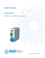
LDD240-WU  

240 W Universal DC-DC Converter

7

4.7 MODBUS

LDD240-WU communicates through Modbus/RTU as specified on “MODBUS over Serial Line” and “MODBUS APPLICATION PROTOCOL 
SPECIFICATION” documents available on http://www.modbus.org/.

Table 1 contains the field types and Table 2 the mapped fields.

TYPE

MODBUS FUNCTION CODES 

DESCRIPTION

READ

WRITE

BIT

1, 2

5, 15

Single bit with value 0 or 1

SINT16

3, 4

6, 16

Signed 16 bit value (2’s complement)

UINT16

3, 4

6, 16

Signed 16 bit value (2’s complement)

Table 1.  Modbus types

ADDRESS 

TYPE 

R/W 

UNIT 

MIN. 

MAX. 

DESCRIPTION 

SETTINGS  

0x1000 

UINT16 

R/W 

99 

Modbus address. 

0x1010 

UINT16 

R/W 

0.01 

4.5 

57 

Nominal output voltage [V]. 

0x1011 

UINT16 

R/W 

0.1 

11 

Maximal output current [A]. 

0x1012 

UINT16 

R/W 

Operating mode (§3.1): 
1. Single 
2. Parallel 

0x1013 

UINT16 

R/W 

Current limitation (§3.2): 
1. Hiccup 
Constant current 

0x1014 

UINT16 

R/W 

Output enable.  
0: Disabled 
1: Enabled 

METERING 

0x2000 

SINT16 

0.1V 

60 

Output voltage [V]. 

0x2001 

SINT16 

0.1V 

15 

Output current [A]. 

0x2002 

SINT16 

0.1V 

360 

Output power [W]. 

0x2003 

SINT16 

0.1V 

60 

Input voltage [V]. 

STATE 

0x4000 

BIT 

DC OK 

0x4001 

BIT 

Output disabled. 

0x4002 

BIT 

Output short circuit. 

0x4003 

BIT 

Output overload. 

0x4004 

BIT 

USB powered. 

0x4005 

BIT 

Over temperature warning. 

0x4006 

BIT 

Over temperature error. 

0x4007 

BIT 

Output over voltage error. 

Table 2.  Modbus fields

Summary of Contents for LDD240-WU

Page 1: ...USER MANUAL belfuse com power solutions LDD240 WU 240 W Universal DC DC Converter ...

Page 2: ...1 Product description 3 2 Features and benefits 3 3 Functional description 4 3 1 Operating mode 4 3 2 Output voltage programming 5 3 3 Current limitation 5 3 4 Output enable 5 3 5 DC OK Relay 5 3 6 Alarms 6 3 7 Modbus 6 4 User interface 8 4 1 LOGS 9 5 Technical Specifications 9 ...

Page 3: ...oltage is 90 of the programmed output voltage value 4 DC Input input voltage supply range is from 12 to 48 VDC 5 Display 2 digits LED display used to program the device and read its status 6 Control Keys 3 push buttons are provided to navigate through menus and to select various functions Figure 1 Front panel view 3 FEATURES AND BENEFITS Up to 240 W output power voltage dependent Converts any volt...

Page 4: ...ode must be set to Single SI see 4 Any voltage between 11 VDC and 55 VDC can be converted in any voltage between 5 VDC and 55 VDC with a max output power of 240 W see datasheet for details 4 1 2 INPUT PROTECTION DEVICES Multiple LDD240 WU can be connected in parallel to increase the output power capabilities and or for redundancy purposes When operating in this mode operating mode must be set to P...

Page 5: ...load OL error message is shown on the display see 3 6 details This cycle is then repeated until the load current demand is not decreased below Imax This operating mode is recommended when powering loads requiring high inrush current demands In case of a direct short circuit on the output the output is switched off in about 0 2 seconds and kept off for 10 seconds Short Circuit SC error message is s...

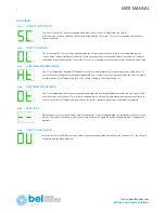
Page 6: ...nusually high levels If no modification of the ambient operating temperature and or load conditions is performed by the user it is highly possible that an Over Temperature Ot error occurs leading to the output switch off 4 6 4 OVER TEMPERATURE ERROR The Over Temperature Ot error message appears when the internal temperature exceeds the safe limits In this case the output is switched off The output...

Page 7: ...N MAX DESCRIPTION SETTINGS 0x1000 UINT16 R W 1 1 99 Modbus address 0x1010 UINT16 R W 0 01 4 5 57 Nominal output voltage V 0x1011 UINT16 R W 0 1 1 11 Maximal output current A 0x1012 UINT16 R W 1 1 2 Operating mode 3 1 1 Single 2 Parallel 0x1013 UINT16 R W 1 1 2 Current limitation 3 2 1 Hiccup Constant current 0x1014 UINT16 R W 1 0 1 Output enable 0 Disabled 1 Enabled METERING 0x2000 SINT16 R 0 1V 0...

Page 8: ... the configuration menus During normal operation the measures are reported Alarms are also reported on the display The layout of the menu is shown below The various options are selected with the 3 keys Figure 5 HMI User can select the measure to show on the display pressing the set button as shown beside The 3 available measures are Output voltage Output current Input voltage Figure 6 HMI measures...

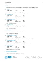
Page 9: ...ot used Active when the output is short circuited 5 1 4 OUTPUT OVERLOAD Modbus address Value1 Value2 0x4003 Inactive 0 Active 1 Not used Active when the output is overloaded 5 1 5 USB POWERED Modbus address Value1 Value2 0x4004 Inactive 0 Active 1 Not used Active when the unit is powered by USB only 5 1 6 OVER TEMPERATURE WARNING Modbus address Value1 Value2 0x4005 Inactive 0 Active 1 Not used Act...

Reviews: