PNEUMATIG.EU - GDYNIA UL.WIELKOPOLSKA 158 -
58 622 49 22
Technical description
26
DRYPOINT® RA 3-160
12.9 Filter dryer
Despite controlled vacuuming, traces of moisture can accumulate in the refrigeration cycle. The filter dryer serves to
absorb this moisture and to bond it.
12.10 Capillary tube
The capillary tube is a copper tube with a reduced diameter which is located between the condenser and the evapora-
tor, serving as a restrictor to reduce the pressure of the refrigerant. The pressure reduction serves to reach an opti-
mum temperature inside of the evaporator. The lower the outlet pressure at the capillary tube, the lower the evapora-
tion temperature.
The length and the inner diameter of the capillary tube are exactly dimensioned to ensure the performance of the
dryer. Settings or maintenance works are not required.
12.11 Aluminium heat exchanger
In the heat exchanger module, the air/air heat exchanger, the air/refrigerant heat exchanger, and the demister in the
form of a condensate separator are accommodated. The compressed-air reverse current in the air/air heat exchanger
guarantees maximum heat transfer. The large cross-section of the flow passage in the heat exchanger module causes
low flow rates. Together with the gas flow in a reverse current, the generous dimensions of the air/refrigerant heat
exchanger allow full evaporation of the refrigerant. This prevents moisture from entering the refrigerating compressor.
The high-performance condensate separator is inside of the heat exchanger module. Maintenance is not necessary
and the coalescence effect aims to achieve a high degree of moisture separation.
12.12 Hot gas bypass valve
At partial load, the valve directly returns a part of the hot gas to the suction line of the refrigerating compressor. The
evaporation temperature/pressure remain constant at approxi2 °C. This injection prevents an ice formation in
the evaporator of the dryer under every load situation.
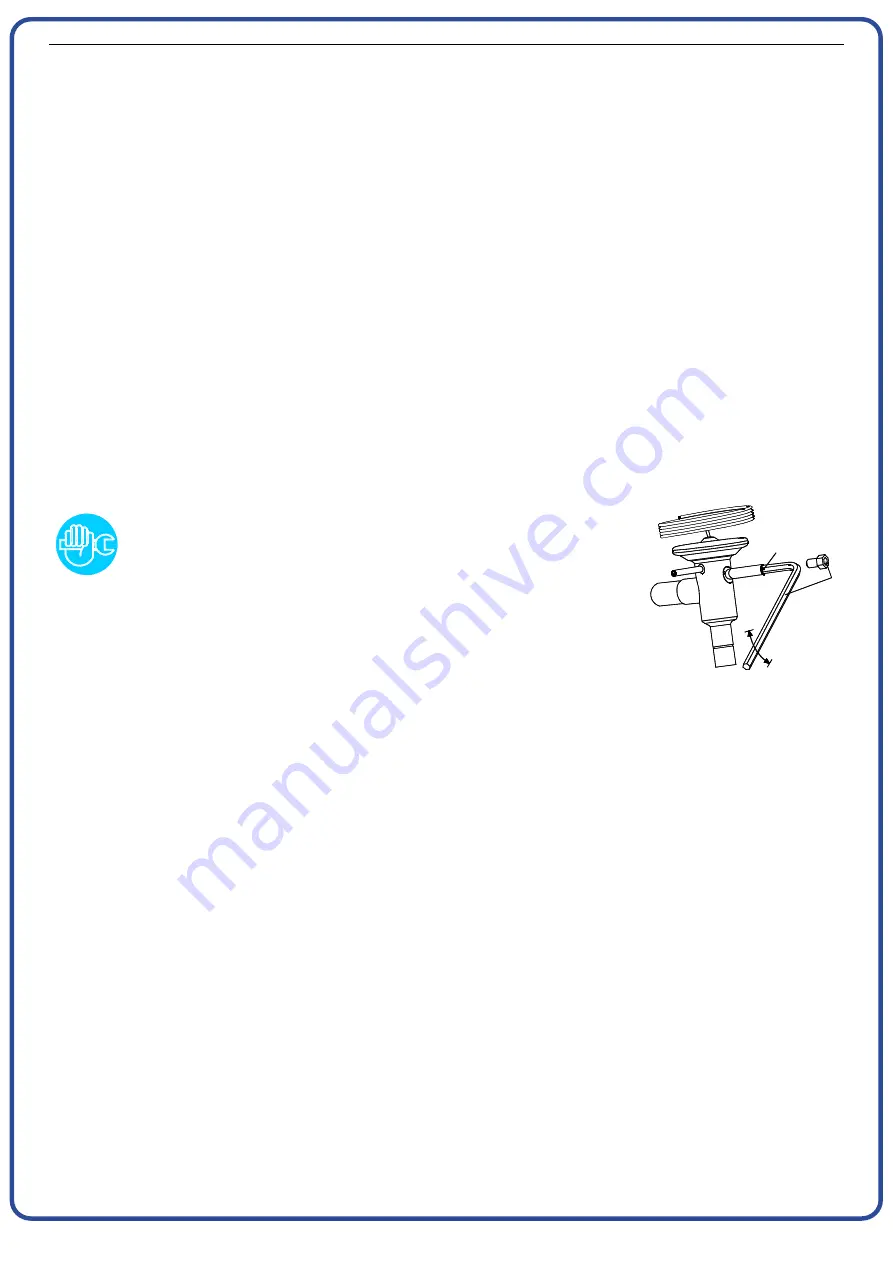
SETTING
The hot gas bypass valve is adjusted in the course of the production test
phase. Normally, no setting is required. Should an adjustment neverthe-
less be necessary, it should be carried out by certified skilled personnel.
WARNING!
The connection of a check gauge to the ¼” Schrader valve should only
take place if the refrigeration system is actually disturbed. Each time a
manometer is connected, parts of the refrigerant are lost.
Turn the adjusting screw (position A in the drawing), without compressed
air flowing through the dryer, until the following values have been
reached:
Hot gas setting (R134.a) :
Temperature 0,5 °C (+0,5 / -0 °K)
Pressure 2,0 bar(g) (+0,1 / -0 bar)
Hot gas setting (R404A) :
Temperature 0,5 °C (+0,5 / -0 °K)
Pressure 5,2 bar(g) (+0,1 / -0 bar)
A
4 mm
5/32 in.
+
-
V
LY
0
00
1
PNEUMATIG


