Installation and operating manual
EN
16 BEKOMAT
®
3/6 CO Ex, 3/6 E Ex
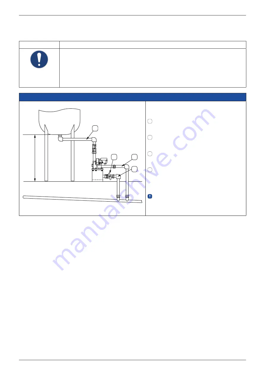
3.3. Installation
The diagrams below show examples of BEKOMAT
®
3/6 installations for various condensation discharge rates.
NOTE
Installation instructions
• Install a separate BEKOMAT
®
at each point where condensate might be produced.
•
Do not use cone-shaped fittings.
• Keep the pipes as short as possible.
•
Do not install filters/dirt trap in the condensate inlet.
• Only install ball valves in the condensate inlet line.
• The venting line must be installed above the highest possible condensate level.
• Observe the minimum installation heights.
BEKOMAT
®
3 CO Ex / 3 E Ex - condensate discharge rate < 360 l/h
1
3
4
2
137 (143) mm*
*Mindesteinbauhöhe (mit Bodenhalter)
1
Upper condensate inlet (Ø ≥ ¾")
Permanently installed pipe at a continuous
gradient (≥ 1°).
2
Manual drain (Ø ≥ ¼") (recommended
)
Permanently installed pipe at a continuous
gradient (≥ 1°)
3
Condensate discharge of solenoid valve
(Ø ≥
½")
Permanently installed pipe at a
continuous gradient (≥ 1°)
4
Condensate discharge of manual drain
(Ø ≥ ¼")
Permanently installed pipe at a continuous
gradient (≥ 1°)
We recommend installing a floor bracket.


