3
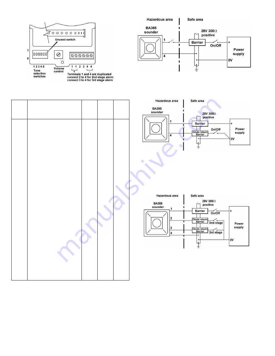
Fig 3 Location of field terminals and controls.
Tone
Number
Tone description
Switch
Settings
1 2 3 4 5
Second
Stage
Alarm
Third
Stage
alarm
Tone 1
Tone 2
Tone 3
Tone 4
Tone 5
Tone 6
Tone 7
Tone 8
Tone 9
Tone 10
Tone 11
Tone 12
Tone 13
Tone 14
Tone 15
Tone 16
Tone 17
Tone 18
Tone 19
Tone 20
Tone 21
Tone 22
Tone 23
Tone 24
Tone 25
Tone 26
Tone 27
Tone 28
Tone 29
Tone 30
Tone 31
Tone 32
Continuous 1000Hz
Toxic gas alarm
Alternating 800/1000Hz at 0.25s intervals
Slow whoop 500/1200Hz at 0.3Hz
with 0.5s gap repeated
Sweeping 500/1000Hz at 1Hz
Continuous 2400Hz
Sweeping 2400/2900Hz at 7Hz
Sweeping 2400/2900Hz at 1Hz
Siren 500/1200/500Hz at 0.3Hz
Sawtooth 1200/500Hz at 1Hz
Alternative 2400/2900Hz at 2Hz
Intermittent 1000Hz at 0.5Hz
General
Alarm
Alternating 800/1000Hz at 0.875Hz
Intermittent 2400Hz at 1Hz
Intermittent 800Hz 0.25s on, 1s off
Continuous 800Hz
Intermittent 550Hz 150nS on, 150ms off
Alternating 544Hz (100ms) /
440Hz (400ms)
Intermittent 660Hz 1.8s on, 1.8s off
1400Hz to 1600Hz sweep up over 1s
1600Hz to 1400Hz sweep down over 0.5s
Continuous 660Hz
Alternating 554/440Hz at 1Hz
Intermittent 544Hz at 0.875Hz
800Hz pulsing at 2Hz
Sweeping 800/1000Hz at 50Hz
Sweeping 2400/2900Hz at 50Hz
Simulated bell
Continuous 554Hz
Continuous 440Hz
Sweeping 800/1000Hz at 7Hz
420Hz repeating 0.625s off
Australian alert signal
1200/400Hz at 1Hz
Prepare to abandon platform
Sweeping 500/1200Hz 3.75s on, 0.25off
15Hz
Australian evacuation signal
0 0 0 0 0
1 0 0 0 0
0 1 0 0 0
1 1 0 0 0
0 0 1 0 0
1 0 1 0 0
0 1 1 0 0
1 1 1 0 0
0 0 0 1 0
1 0 0 1 0
0 1 0 1 0
1 1 0 1 0
0 0 1 1 0
1 0 1 1 0
0 1 1 1 0
1 1 1 1 0
0 0 0 0 1
1 0 0 0 1
0 1 0 0 1
1 1 0 0 1
0 0 1 0 1
1 0 1 0 1
0 1 1 0 1
1 1 1 0 1
0 0 0 1 1
1 0 0 1 1
0 1 0 1 1
1 1 0 1 1
0 0 1 1 1
1 0 1 1 1
0 1 1 1 1
1 1 1 1 1
Tone 31
Tone 17
Tone 2
Tone 6
Tone 3
Tone 7
Tone 10
Tone 2
Tone 15
Tone 7
Tone 31
Tone 4
Tone 15
Tone 4
Tone 2
Tone 18
Tone 2
Tone 2
Tone 2
Tone 2
Tone 2
Tone 2
Tone 6
Tone 29
Tone 29
Tone 2
Tone 26
Tone 2
Tone 7
Tone 32
Tone 11
Tone 26
Tone 11
Tone 5
Tone 5
Tone 5
Tone 27
Tone 5
Tone 5
Tone 5
Tone 2
Tone 5
Tone 1
Tone 5
Tone 5
Tone 5
Tone 5
Tone 5
Tone 27
Tone 5
Tone 5
Tone 5
Tone 5
Tone 5
Tone 5
Tone 5
Tone 5
Tone 1
Tone 5
Tone 5
Tone 5
Tone 5
Tone 1
Tone 1
Table 1 Function of tone selection switches
6. ELECTRICAL SYSTEM DESIGN FOR INSTALLATION IN
HAZARDOUS AREAS USING ZENER BARRIERS
6.1 Single stage alarm
If the control switch is in the positive supply, or the power supply is being
turned on and off, only a single channel Zener barrier is required as
shown in Fig 4. This circuit may also be used if the sounder is being
controlled from the hazardous area by a mechanically activated switch
complying with the requirements for simple apparatus. See 4.5
Fig 4 Single stage alarm using single channel barrier.
If the negative side or the power supply and one side of the control switch
are earthed, the circuit shown in Fig 5 may be used.
Fig 5 Single stage alarm using two channel barrier.
6.2 Multi-stage alarm
Connecting terminal 2 to 0V activates the second stage alarm, and
similarly terminal 3 for the third stage alarm. Fig 6 shows how diode return
barrier(s) may be used to control the sounder from the safe area. If only
two stages of alarm are required the third stage barrier should be omitted,
the 28V 300ohm barrier and the single diode return channel may then be
contained in one package.
Fig 6 Multi stage alarm using Zener barriers.
7. ELECTRICAL SYSTEM DESIGN FOR INSTALLATION IN
HAZARDOUS AREAS USING GALVANIC ISOLATORS.
Galvanic isolators although more expensive than Zener barriers, do not
require a high integrity earth connection. For small systems where a high
integrity earth is not already available, the use of galvanic isolators often
reduces the overall installation cost and simplifies design.
7.1 Single stage alarm
The BA385-IIB and the BA385-IIC sounders may be powered by any EEx
ia certified galvanic isolator having output parameters within the limits
specified in section 4.4. The sounder may be controlled by turning the
galvanic isolator on and off, or from the hazardous area by a mechanically
activated switch complying with the requirements for simple apparatus.
See 4.5


