background image

Programming

Operating Instructions 1225-6 - 01.0 - 01/2021

45

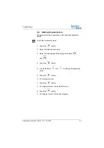
5.5.4

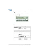
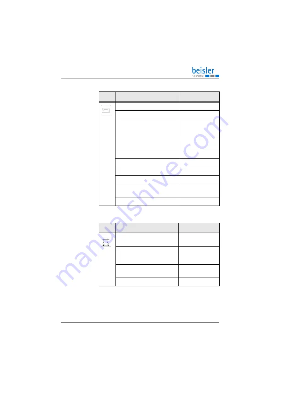
Setting machine parameters

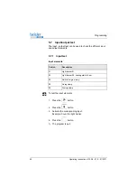
5.5.5

Setting the swivel device

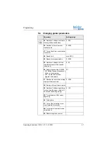
Parameter

Setting range

30

: Set sewing speed

0 - 8500

31

: switch manual sewing on/off

0/1

32

: Number of stitches specifying for 

how long table blowing will remain 
switched on

0 - 400

44

: Number of stitches until the edge 

guide is lowered

0 - 200

60

: Soft start speed

500 - 5000

61

: Switch soft start on/off

0/1

76

: Switch start via light barrier on/off 0/1

77

: Switch auto start on/off

0/1

78

: Number of stitches after which 

auto start will start

0 - 400

98

: Switch the lining clamp on/off

0/1

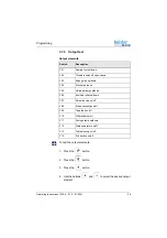
Parameter

Setting range

62

: Number of stitches after which 

the blade will extend

0 - 00

63

: Number of stitches specifying 

for how long the blade will remain 
retracted

0 - 00

64

: Switch the swiveling of the 

stacker on/off

0/1

69

: Light barrier start

0/1

Summary of Contents for 1225-6

Page 1: ...1225 6 Operating Instructions ...

Page 2: ... GmbH and protected by copyright Any reuse of these contents including extracts is prohibited without the prior written approval of Dürkopp Adler GmbH Copyright Dürkopp Adler GmbH 2021 IMPORTANT READ CAREFULLY BEFORE USE KEEP FOR FUTURE REFERENCE ...

Page 3: ...a Quick stop 22 4 5 Operating the machine head 23 4 6 Removing and placing the fabric sliding plate 23 4 7 Setting the differential feed 24 4 8 Operating the fusing station 25 4 8 1 Inserting the fusing tape 25 4 8 2 Switching on the fusing station 27 4 8 3 Fusing of knee lining and front trousers 28 4 8 4 Setting the fusing tape feed 30 4 8 5 Cleaning the stamp 31 4 9 Setting the edge guide 32 4 ...

Page 4: ... Loading data from the USB key 56 5 11 6 Comparing data stored on the USB key with the data of the control 57 5 11 7 Deleting data from the USB key 58 5 11 8 Loading the software version from the USB key 58 6 Maintenance 61 6 1 Cleaning 62 6 2 Lubricating 63 6 3 Servicing the pneumatic system 66 6 3 1 Setting the operating pressure 66 6 3 2 Draining the water condensation 67 6 3 3 Cleaning the fil...

Page 5: ... 0 01 2021 3 7 9 3 Setting the operating pressure 81 7 10 Performing a test run 82 8 Decommissioning 83 9 Disposal 85 10 Troubleshooting 87 10 1 Customer Service 87 10 2 Messages of the software 87 10 3 Errors in sewing process 89 11 Technical data 91 ...

Page 6: ...Table of Contents 4 Operating Instructions 1225 6 01 0 01 2021 ...

Page 7: ... store them in a place where they are readily available 1 1 For whom are these instructions intended These instructions are intended for Operators This group is familiar with the machine and has access to the instructions Specifically chapter Operation p 19 is important for the operators Specialists This group has the appropriate technical training for performing maintenance or repairing malfuncti...

Page 8: ...g Cover Specifies which covers must be disassembled in order to access the components to be set Steps to be performed when operating the machine sewing and equipping Steps to be performed for service maintenance and installation Steps to be performed via the software control panel The individual steps are numbered First step Second step The steps must always be followed in the specified order List...

Page 9: ... symbols levels of danger and their signal words are described separately in the chapter Safety p 9 Location information If no other clear location information is used in a figure indications of right or left are always from the user s point of view 1 3 Other documents The machine includes components from other manufacturers Each manufacturer has performed a hazard assessment for these purchased p...

Page 10: ...se Unauthorized modifications to the machine Use of untrained personnel Use of unapproved parts Transport Dürkopp Adler cannot be held liable for breakage and transport damages Inspect the delivery immediately upon receiving it Report any damage to the last transport manager This also applies if the packaging is not damaged Leave machines equipment and packaging material in the con dition in which...

Page 11: ...following work switch off the machine at the main switch or disconnect the power plug Replacing the needle or other sewing tools Leaving the workstation Performing maintenance work and repairs Threading Missingorfaultypartscouldimpairsafetyanddamagethemachine Only use original parts from the manufacturer Transport Use a lifting carriage or forklift to transport the machine Raise the machine max 20...

Page 12: ...epairs Perform work on electrical equipment Only authorized persons may work on the machine and must first have understood these instructions Operation Check the machine during operating for any externally visible damage Stop working if you notice any changes to the machine Report any changes to your supervisor Do not use a damaged machine any further Safety equipment Safety equipment should not b...

Page 13: ...y describe Symbols The following symbols indicate the type of danger to personnel Signal word Meaning DANGER with hazard symbol If ignored fatal or serious injury will result WARNING with hazard symbol If ignored fatal or serious injury can result CAUTION with hazard symbol If ignored moderate or minor injury can result CAUTION with hazard symbol If ignored environmental damage can result NOTICE w...

Page 14: ...y or even death if ignored This is what a warning looks like for a hazard that could result in serious or even fatal injury if ignored Puncture Crushing Environmental damage Symbol Type of danger DANGER Type and source of danger Consequences of non compliance Measures for avoiding the danger WARNING Type and source of danger Consequences of non compliance Measures for avoiding the danger ...

Page 15: ... result in property damage if ignored This is what a warning looks like for a hazard that could result in environmental damage if ignored CAUTION Type and source of danger Consequences of non compliance Measures for avoiding the danger NOTICE Type and source of danger Consequences of non compliance Measures for avoiding the danger CAUTION Type and source of danger Consequences of non compliance Me...

Page 16: ...Safety 14 Operating Instructions 1225 6 01 0 01 2021 ...

Page 17: ... 01 0 01 2021 15 3 Machine description 3 1 Components of the machine Fig 1 Components of the machine 1 Reel stand 2 Swivel device 3 Machine head 4 Stacker 5 Extraction system 6 Control 7 Compressed air maintenance unit 8 Fusing station 9 Control panel ...

Page 18: ... intended for industrial use The machine may only be set up and operated in dry conditions on well maintained premises If the machine is operated on premises that are not dry and well maintained then further measures may be required which must be compatible with DIN EN 60204 31 Only authorized persons may work on the machine Dürkopp Adler cannot be held liable for damages resulting from improper u...

Page 19: ...ctions 1225 6 01 0 01 2021 17 3 3 Declaration of Conformity ThemachinecomplieswithEuropeanregulationsensuringhealth safety and environmental protection as specified in the declara tion of conformity or in the declaration of incorporation ...

Page 20: ...Machine description 18 Operating Instructions 1225 6 01 0 01 2021 ...

Page 21: ...machine for operation Complete the following steps in preparation of sewing before starting to work Inserting changing the needle Threading the needle thread Inserting and winding on the hook thread Setting the thread tension Inserting the fusing tape WARNING Risk of injury from moving cutting and sharp parts Crushing cutting and punctures are possible If possible make preparations only when the m...

Page 22: ...ching on and off the machine To switch on and off the machine 1 Set the main switch 1 to position I The machine switches on The control loads the machine program The basic display appears in the display of the control panel 2 Turn the main switch 1 to the O position The machine switches off 1 Main switch ...

Page 23: ...used to immediately stop all working steps on the machine e g after an operating mistake Fig 3 Switching on Quick stop To switch on Quick stop 1 Press the Quick stop switch 1 All working steps on the machine are immediately stopped 2 Turn the main switch to the O position The machine switches off 1 Quick stop switch ...

Page 24: ...r a Quick stop 1 Set the main switch to position I The machine switches on 2 Unlock the Quick stop switch 1 The control loads the machine program The basic display appears in the display of the control panel CAUTION Risk of injury from sharp and moving parts Puncture or crushing possible Do not put the machine back into operation until AFTER you corrected the fault 1 Quick stop switch ...

Page 25: ...ons are provided in the machine accessory pack 4 6 Removing and placing the fabric sliding plate Fig 5 Removing and placing the fabric sliding plate The fabric sliding plate 1 is held in the tabletop cut out by the magnets 3 The edge guide 2 is assembled to the fabric sliding plate Removing the fabric sliding plate To remove the fabric sliding plate 1 Carefully pull the edge guide 2 up and off the...

Page 26: ...3 from the top 4 7 Setting the differential feed Fig 6 Setting the differential feed Setting the permanent differential The permanent differential is active during the entire sewing pro cess The adjusting range is between 10 and 6 To set the permanent differential 1 Adjust the lever 1 Greater fullness Move the lever 1 further into the plus range Less to no fullness Move the lever 1 further into th...

Page 27: ...he control and is only active in specific seam sections The adjusting range is between 0 and 16 To set the additional differential 1 Adjust the lever 2 Greater fullness Move the lever 2 further into the plus range 4 8 Operating the fusing station 4 8 1 Inserting the fusing tape Fig 7 Inserting the fusing tape 1 1 Flap 2 Guide 3 Handle 4 Tape ...

Page 28: ...nwinding 3 Push the right supporting disk back onto the shaft until it catches 4 Feed the fusing tape 4 through guide 2 5 Fold up the flap 1 Fig 8 Inserting the fusing tape 2 6 Separate the fusing tape 4 from the backing material 7 7 Guide the fusing tape 4 under the flap 1 and draw it under the clamp 5 8 Guide the backing material 7 downwards behind the trans port roller 6 9 Close the flap 1 1 Fl...

Page 29: ...n To switch on the fusing station 1 Set the main switch 1 to position I The machine switches on 2 Press the toggle switch 2 to the I position The toggle switch is lit Information The lower value green numbers indicates the preset heating value Theuppervalue red numbers indicatesthecurrentheatingvalue 1 Main switch 2 Toggle switch ...

Page 30: ...ment of the knee lining during the sewing process a bonding point has to be set with the fusing station fusing the lining at the correct position CAUTION Risk of injury from hot fusing stamp Risk of burns Do not touch the area around the fusing station as the lower stamp is very hot 1 Clamp 2 Knee lining 3 Tape 4 Net like fusing tape 5 Button 6 Button 7 Upper stamp 8 Trousers part ...

Page 31: ...is separated from the backing material 3 Position the trousers part 8 and align it relative to the knee lining 2 4 Press the button 4 The upper stamp 7 moves downwards while the lower heated stamp moves upwards The stamps press trousers part 8 and knee lining 2 together with the fusing tape lying in between After the preset fusing time the upper stamp 7 and the clamp 1 are lifted automatically and...

Page 32: ... fusing tape feed A lever can be used to set the amount of fusing tape that will be fed Fig 11 Setting the fusing tape feed To set the fusing tape feed 1 Select the desired hole on the lever 1 more fusing tape select a higher hole less fusing tape select a lower hole 1 Lever ...

Page 33: ...the stamp To clean the stamp 1 Actuate the toggle switch 1 The lower stamp 2 moves up 2 Clean the stamp 3 Actuate the toggle switch 1 The lower stamp 2 moves down CAUTION Risk of injury from hot fusing stamp Risk of burns Allow the stamp to cool off before cleaning it 1 Toggle switch 2 lower stamp ...

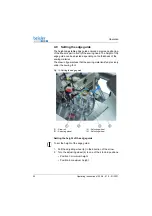
Page 34: ...ckness of the sewing material The draw roll guarantees that the sewing material is fed precisely under the sewing foot Fig 13 Setting the edge guide Setting the height of the edge guide To set the height of the edge guide 1 Pull the adjusting wheel 4 in the direction of the arrow 2 Turn the adjusting wheel 4 to one of the 4 lock in positions Position 1 minimum height Position 4 maximum height 1 Dr...

Page 35: ...ide To set the fine adjustment of the edge guide 1 Turn the adjusting wheel 3 Setting the pressure of the draw roll To set the pressure of the draw roll 1 Turn the adjusting wheel 2 Increase the pressure of the draw roll 1 turn clockwise Decrease the pressure of the draw roll 1 turn counterclockwise ...

Page 36: ...cker The finished workpieces are stacked on the throw over stacker Stacking the sewing material manually To stack the sewing material manually 1 Press the F2 button 2 A stacking process is carried out CAUTION Risk of injury from moving parts Crushing possible Do NOT reach into the working area of the throw over stacker during stacking 1 Pedal 2 Button F2 ...

Page 37: ...4 10 2 Setting the air nozzles in the tabletop Fig 15 Setting the air nozzles in the tabletop The air nozzles 1 embedded in the tabletop support the precise stacking of the sewing material To set the air nozzles in the tabletop 1 Turn the adjusting wheel 2 Increased intensity of the air blast turn clockwise Reduced intensity of the air blast turn counterclockwise 1 Air nozzles 2 Adjusting wheel ...

Page 38: ...re the sewing material is positioned straight under the edge guide 2 Important The edge guide 2 lowers when the sewing material 4 is moved underthe lightbarrier 1 Thesewingprocess startsautomatically 4 Slide the sewing material 4 under the light barrier 1 The sewing process starts When the sewing process ends the stamps 3 are lowered and the sewing material 4 is stacked 1 Light barrier 2 Edge guid...

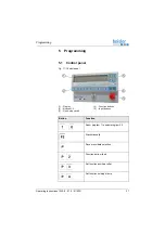
Page 39: ...ntrol panel Fig 17 Control panel 1 Display 2 Buttons 1 0 3 Quick stop switch 4 Function buttons 5 Input buttons Button Function Seam program 1 to seam program 20 Stack manually Save menu data selection Function bottom feed Set function auxiliary roller Set function holding stamp ...

Page 40: ...25 6 01 0 01 2021 Set machine parameters Set function swivel device Sewing stop in the seam Input output test Program sequence S Create programs Prg Set global parameters Enter Select parameters scroll Change parameter values Button Function ...

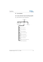
Page 41: ...te 5 Maschinenparameter einstellen Taste 6 Ausschwenker einstellen Taste 7 Nähstopp in der Naht Taste 8 Input Output Test Taste 9 Programme erstellen Sequenzen erstellen Taste 0 Globale Parameter einstellen Switch on main switch Start screen to Call up seam programs Menu selection Button F2 Manual stacking Button 2 Set bottom feed Button 3 Set auxiliary roller Button 4 Set holding stamp Button 5 S...

Page 42: ...seam program is loaded 5 2 3 Calling up the parameter menu To call up the parameter menu 1 Switch on the main switch The machine starts up The control initializes The seam program previously used is loaded 2 Press the button The selection menu is loaded 3 Press one of the buttons to The display changes over to the corresponding function 5 2 4 Manual stacking To stack manually 1 Select the seam pro...

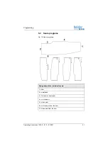
Page 43: ...tructions 1225 6 01 0 01 2021 41 5 3 Seam programs Fig 19 Seam programs Designation of the individual seams 1 hem 2 waistband 3 fly seam or seat seam 4 crotch seam 5 side seam 6 crotch seam from the hem 7 side seam from the hem ...

Page 44: ...rams 1 Seam program number 2 Seam number Seam program Description 001 Crotch seam from the waistband 002 Side seam from the waistband 003 Crotch seam from the hem 004 Side seam from the hem 005 Side seam with prefabricated pocket from the waistband Manual start 006 Side seam with prefabricated pocket from the hem Automatic start up to the pocket Finish seam manually 007 Crotch seam and side seam a...

Page 45: ...et the parameter values 1 Press the button 2 Select the desired menu item 3 Select the desired parameter using the buttons and 4 Press the button 5 Use the buttons and to change the parameter value 6 Press the button The setting is saved 7 Press the button The display returns to the selection menu 8 Press the button The display returns to the seam program ...

Page 46: ...path 2 ON OFF 75 Fullness of path 3 ON OFF Parameter Setting range 13 Number of stitches after which the auxiliary roller will be lowered 0 400 14 Number of stitches specifying for how long the auxiliary roller will remain lowered 0 300 Parameter Setting range 15 Time when the holding stamp is lowered 2 20 16 Duration for which the warp separator will remain switched on 0 100 17 Switch the throw o...

Page 47: ... until the edge guide is lowered 0 200 60 Soft start speed 500 5000 61 Switch soft start on off 0 1 76 Switch start via light barrier on off 0 1 77 Switch auto start on off 0 1 78 Number of stitches after which auto start will start 0 400 98 Switch the lining clamp on off 0 1 Parameter Setting range 62 Number of stitches after which the blade will extend 0 00 63 Number of stitches specifying for h...

Page 48: ...tch the sewing foot lift in the seam on off 0 1 86 Length of seam path 2 0 00 87 Switch the speed reduction in seam path 2 on off 0 1 88 Speed reduction in seam path 2 0 7000 89 Switch stop in seam on off 0 1 90 Switch the sewing foot lift in the seam on off 0 1 86 Length of seam path 3 0 00 87 Switch the speed reduction in seam path 3 on off 0 1 88 Speed reduction in seam path 3 0 7000 89 Switch ...

Page 49: ...til the thread tensioner will be opened seam end 0 50 56 Seam programming ON OFF ON Define the seam sequences in the current program OFF create the next free program with seams 0 1 57 Duration for which the holding stamp will remain down 0 2000 58 Display of the software version 59 Number of stitches specifying for how long the seam chain will be sucked seam beginning 0 150 65 Thread tension lift ...

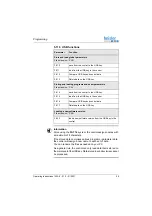
Page 50: ...tput elements 5 7 1 Input test Input elements To test the input elements 1 Press the button 2 Press the button 3 Activate the corresponding input Example Cover the light barrier 4 Press the button The program is quit Switch Description 01 Light barrier 01 03 Light barrier 03 sewing start of hem 05 Switch Program stop 08 Lining clamp 09 Fusing stamp ...

Page 51: ...lect the desired output element Switch Description Y01 Sewing foot up down Y02 Thread tension lift open closed Y03 Edge guide up down Y04 Stacker pulse on Y05 Holding stamp up down Y06 Auxiliary roller up down Y07 Swivel device on off Y08 Blade swiveling on off Y09 Tape feed on off Y10 Differential on off Y11 Fusing stamp up down Y12 Warp separator on off Y13 Table blowing on off Y14 Dirt suction ...

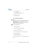
Page 52: ...delete an existing seam program you must set the global parameter 56 to the value 0 p 47 Doing so switches off seam programming preventing existing programs from being altered inadvertently To create a seam program 1 Press the button 2 Press the button Prg programs 3 Briefly press the button 2x 4 Use one of the buttons to select a seam 5 Press the button The selected seam is stored 6 Use one of th...

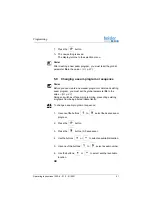
Page 53: ...a new seam program or delete an existing seam program you must set the global parameter 56 to the value 0 p 47 Doing so switches off seam programming preventing existing programs from being altered inadvertently To change a seam program or sequence 1 Useoneofthebuttons to selectthedesiredseam program 2 Press the button 3 Press the button S 0 sequence 4 Use thebuttons or toselectan available locati...

Page 54: ...ored and the display returns to the selection menu 5 10 Deleting a seam program To delete a seam program 1 Press the button 2 Press the button 3 Press the button The display shows DELETE 4 Press the button The seam program has been deleted 5 Press the button The display returns to the selection menu ...

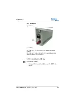
Page 55: ...key The USB key 1 is used to transfer and store the machine software The USB key 1 makes it possible to transfer program and parameter data to other machines 5 11 1 Formatting the USB key To format the USB key 1 Use your PC to format the USB key with the FAT 16 file system 1 USB key ...

Page 56: ...ey To initialize the USB key 1 Switch off the main switch 2 Plug the USB key 1 into the control 3 Press and hold the button 4 Switch on the main switch The display shows the message USB DEV DETECT 5 Press and hold the button until the display shows the message SERVICE CODE 6 Enter code 3112 7 Press the button 1 USB key ...

Page 57: ...heUSBkey Data storedinsubdirectoriescannot be processed Parameter Function Store and load global parameters File extension PAR F 510 save from the control to the USB key F 511 load from the USB key to the control F 512 Compare USB key and control data F 513 Delete data on the USB key Storing and loading programs and seam parameters File extension PAY F 514 save from the control to the USB key F 51...

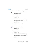
Page 58: ...e control appears 4 Press the button The data is written to the USB key 5 11 5 Loading data from the USB key To load data from the USB key 1 Enter the desired parameter 2 Press the button The cursor flashes 3 Press the button The name of the first file stored on the USB key appears 4 Select the desired file using the buttons or 5 Press the button The message READ DATA YES E appears 6 Press the but...

Page 59: ...n The file name assigned by the control appears 3 Press the button The message READ DATA YES E appears 4 Press the button The data stored on the USB key is compared with the data of the control The message READ DATA appears The result of the comparison is displayed DATA OK The data stored on the USB key is identical to the data of the control DATA DIFFERENT The data stored on the USB key is not id...

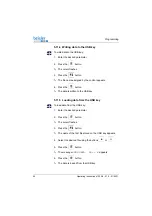
Page 60: ...red on the USB key appears 4 Select the desired file using the buttons or 5 Press the button The data is deleted from the USB key The message READY appears 5 11 8 Loading the software version from the USB key To load the software version from the USB key 1 Enter parameter 523 2 Press the button The cursor flashes 3 Press the button The name of the first file stored on the USB key appears 4 Select ...

Page 61: ...Wait for approx 3 seconds until the message disappears 9 Press the button 2x The cursor flashes 10 Press the button The name of the first file stored on the USB key appears 11 Select the desired program file using the buttons or 12 Press the button The message READ DATA YES E appears 13 Press the button The data is read from the USB key 14 Switch off and on the machine again The new software versi...

Page 62: ...Programming 60 Operating Instructions 1225 6 01 0 01 2021 ...

Page 63: ...ructions Maintenance intervals WARNING Risk of injury from sharp parts Punctures and cutting possible Prior to any maintenance work switch off the machine or set the machine to threading mode WARNING Risk of injury from moving parts Crushing possible Prior to any maintenance work switch off the machine or set the machine to threading mode Work to be carried out Operating hours 8 40 160 500 Remove ...

Page 64: ...d the compressed air gun so that the particles do not fly close to people Make sure no particles fly into the oil pan NOTICE Property damage from soiling Lint and thread remnants can impair the operation of the machine Clean the machine as described NOTICE Property damage from solvent based cleaners Solvent based cleaners will damage paintwork Use only solvent free substances for cleaning ...

Page 65: ... 2 Lubricating 1 Thread guides 2 Suction container CAUTION Risk of injury from contact with oil Oil can cause a rash if it comes into contact with skin Avoid skin contact with oil If oil has come into contact with your skin wash the affected areas thoroughly NOTICE Property damage from incorrect oil Incorrect oil types can result in damage to the machine Only use oil that complies with the data in...

Page 66: ...ollowing specifications Viscosity at 40 C 10 mm2 s Flash point 150 C You can order the lubricating oil from our sales offices using the following part numbers CAUTION Risk of environmental damage from oil Oil is a pollutant and must not enter the sewage system or the soil Carefully collect up used oil Dispose of used oil and oily machine parts in accordance with national regulations Container Part...

Page 67: ... the lubrication of the machine head Fig 24 Checking the lubrication of the machine head To check the lubrication of the machine head 1 Check the oil level in the inspection window 1 2 If necessary top off the oil Operating Instructions Machine head 1 Inspection glass ...

Page 68: ...ting pressure cannot deviate by more than 0 5 bar Check the operating pressure on a daily basis Fig 25 Setting the operating pressure To set the operating pressure 1 Pull the pressure controller 1 up NOTICE Property damage from incorrect setting Incorrect operating pressure can result in damage to the machine Ensure that the machine is only used when the operating pressure is set correctly 1 Press...

Page 69: ...aining the water condensation Water condensation accumulates in the water separator 2 of the pressure controller Proper setting Water condensation must not rise up to the level of the filter element 1 Check the water level in the water separator 2 on a daily basis Fig 26 Draining the water condensation NOTICE Property damage from excess water Excess water can cause damage to the machine Drain wate...

Page 70: ... completely 4 Allow water to drain into the collection tray 5 Tighten the drain screw 3 6 Connect the machine to the compressed air supply 6 3 3 Cleaning the filter element Fig 27 Cleaning the filter element NOTICE Damage to the paintwork from solvent based cleaners Solvent based cleaners damage the filter Use only solvent free substances for washing out the filter tray 1 Filter element 2 Water se...

Page 71: ...tor 2 4 Loosen the filter element 1 5 Blow out the filter element 1 using the compressed air gun 6 Wash out the filter tray using benzine 7 Tighten the filter element 1 8 Tighten the water separator 2 9 Tighten the drain screw 3 10 Connect the machine to the compressed air supply 6 4 Parts list Apartslistcanbe orderedfromDürkopp Adler Orvisitourwebsite for further information at www duerkopp adler...

Page 72: ...Maintenance 70 Operating Instructions 1225 6 01 0 01 2021 ...

Page 73: ...ting up the machine Protective foils Lashing straps at reel stand and stand Lashing strap at throw over stacker WARNING Risk of injury from cutting parts Cutting injuries may be sustained while unpacking and setting up the machine Only qualified specialists may set up the machine Wear safety gloves WARNING Risk of injury from moving parts Crushing injuries may be sustained while unpacking and sett...

Page 74: ...ing parts The tabletop can sink under its own weight when the screws on the stand bars are loosened Crushing possible Ensure that your hands are not jammed when loosening the screws CAUTION Risk of musculoskeletal damage from incorrect setting The operator can sustain musculoskeletal damage if failing to comply with the ergonomic requirements Adjust the working height to the body height of the per...

Page 75: ...8 Setting the working height To set the working height 1 Loosen the screws 1 on the stand bars 2 Set the tabletop to the desired height Important Pull out or push in the tabletop evenly at both sides to prevent it from jamming 3 Tighten the screws 1 1 Screws ...

Page 76: ...ctions 1225 6 01 0 01 2021 7 4 Assembling the reel stand Fig 29 Assembling the reel stand To assemble the reel stand 1 Insert the real stand tube 1 into the bracket 3 2 Tighten the screws 2 1 Reel stand tube 2 Screws 3 Bracket ...

Page 77: ...mbling the control panel Fig 30 Assembling the control panel To assemble the control panel 1 Loosen the screws 2 2 Pull up the supporting tube 1 along with the control panel 3 as far as it will go 3 Tighten the screws 2 1 Supporting tube 2 Screws 3 Control panel ...

Page 78: ...ng the throw over stacker 1 To assemble the throw over stacker 1 Move the throw over stacker with bracket 2 up to the machine 2 Tighten the bracket 2 to the machine using the screws 1 Do not yet tighten the screws 1 all the way 1 Screws 2 Bracket 3 Compressed air line 4 Grounding wire 5 Compressed air line ...

Page 79: ...ver stacker 2 3 Align the throw over stacker such that the smoother 7 is parallel to the edge of the tabletop 6 4 Tighten the screws 1 5 Tighten the grounding wire 4 at the throw over stacker 6 Slip the compressed air lines 3 and 5 onto the junction 6 Edge of the tabletop 7 Smoother ...

Page 80: ...ligning the sewing material surfaces Fig 33 Aligning the sewing material surfaces To align the sewing material surfaces 1 Loosen the screws 1 2 Set the sewing material surfaces 2 to the desired height 3 Tighten the screws 1 1 Screws 2 Sewing material surfaces ...

Page 81: ... motor mustcorrespond to the mains voltage Establishing the electrical connection To establish the electrical connection 1 Connect the mains plug DANGER Risk of death from live components Unprotected contact with electricity can result in serious injuries or death Only qualified specialists may perform work on electrical equipment ...

Page 82: ...e compressed air maintenance unit 1 Connect the connection hose to the compressed air supply using a hose coupling R 1 4 NOTICE Property damage from oily compressed air Oil particles in the compressed air can cause malfunctions of the machine and soil the sewing material Ensure that no oil particles enter the compressed air supply NOTICE Property damage from incorrect setting Incorrect system pres...

Page 83: ...le operating pressure The operating pressure cannot deviate by more than 0 5 bar Check the operating pressure on a daily basis Fig 34 Setting the operating pressure NOTICE Property damage from incorrect setting Incorrect operating pressure can result in damage to the machine Ensure that the machine is only used when the operating pressure is set correctly 1 Pressure controller 2 Pressure gage ...

Page 84: ...r 1 up 2 Turn the pressure controller until the pressure gage 2 indicates the proper setting Increase pressure turn clockwise Reduce pressure turn counterclockwise 3 Push the pressure controller 1 down 7 10 Performing a test run When setup is complete perform a test run to check the function ality of the machine ...

Page 85: ...rom soiling 6 Cover the control to protect it from soiling 7 Cover the entire machine if possible to protect it from contam ination and damage WARNING Risk of injury from a lack of care Serious injuries may occur ONLY clean the machine when it is switched off Allow ONLY trained personnel to disconnect the machine CAUTION Risk of injury from contact with oil Oil can cause a rash if it comes into co...

Page 86: ...Decommissioning 84 Operating Instructions 1225 6 01 0 01 2021 ...

Page 87: ...able national regulations When disposing of the machine be aware that it consists of a range of different materials steel plastic electronic components etc Follow the national regulations when disposing these materials CAUTION Risk of environmental damage from improper disposal Improper disposal of the machine can result in serious environmental damage ALWAYS comply with the national regulations r...

Page 88: ...Disposal 86 Operating Instructions 1225 6 01 0 01 2021 ...

Page 89: ...ervice duerkopp adler com Internet www duerkopp adler com 10 2 Messages of the software Please contact customer service if an error occurs that is not described here Do not attempt to correct the error yourself Code Meaning Error 3 You should delete the last existing seam in the program currently used Info B1 Switch on the control in boot mode and press the F2 button Info B2 programmed segment num...

Page 90: ...eter that does not exist Info U2 wrong system function Info U3 wrong In Out number Info U4 too many user variables Info U5 too many system variables Info U6 User program does not fit in memory Info U7 wrong or non defined button on control panel Info U8 unknown device address Info U9 fatal exception error Code Meaning ...

Page 91: ...k threading path Needle is bent or sharp edged Replace needle Needle is not inserted correctly into the needle bar Insert the needle correctly into the needle bar The thread used is unsuitable Use recommended thread Thread tensions are too tight for the thread used Check thread tensions Thread guiding parts such as thread tube thread guide or thread take up disk are sharp edged Check threading pat...

Page 92: ...ssembled incorrectly Check the assembly of the reel stand Thread tensions are too tight Check thread tensions Throat plate hook or spread have been damaged by the needle Have parts reworked by qualified specialists Loose stitches Thread tensions are not adjusted to the sewing material the sewing material thickness or the thread used Check thread tensions Needle thread and hook thread have not been...

Page 93: ...04 Hook type Overlock hook Number of needles 1 Needle system B27 Needle strength Nm 80 110 Thread strength Nm Bulked thread 120 Stitch length mm 1 0 mm 5 0 mm Speed maximum min 1 7500 Speed on delivery min 1 7000 Seam clearance mm 6 mm 5 mm 4 mm Mains voltage V 1x230 V Mains frequency Hz 50 60 Operating pressure bar 6 Length mm 1500 Width mm 900 Height mm 1400 Weight kg 120 Power input kVA 0 9 ...

Page 94: ...Technical data 92 Operating Instructions 1225 6 01 0 01 2021 ...

Page 95: ......

Page 96: ... Germany Phone 49 0 521 925 00 Email service duerkopp adler com www duerkopp adler com Subject to design changes Part of the machines shown with additional equipment Printed in Germany Dürkopp Adler GmbH Original Instructions 0791 122740 EN 01 0 01 2021 ...

Reviews: