background image

GN-9289 User Manual 


Page 61 of (70) 

G-series GN-9289 Modbus TCP_UDP Rev. 1.01.docx 

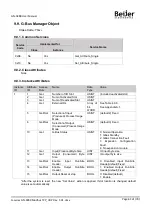
9.9.  G-Bus Manager Object 


Class Code: 70

HEX 


9.9.1. Common Services


Service 

Code


Implementedfor


Service Name


Class


Instance


0x0E 


No 


Yes 


Get_Attribute_Single 


0x10 


No 


Yes 


Set_Attribute_Single 


9.9.2. Class Attributes


None 


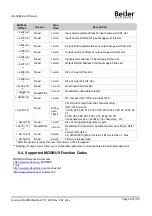
9.9.3. Instance Attributes


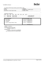
Instance 
ID 

Attribute 
ID 

Access 
Rule 

Name 

Data 
Type 

Value 

Get 

Number of I/O Slot 

USINT 

(include deactivated slot) 

Get 

Num of Activated Slot 

USINT 


Get 

Num of Deactivated Slot 

USINT 


Get 

External IDs 

Array  of 
64 
WORD 

See Table 4.9.6. 
See Appendix A.1. 

Get/Set 

Selection of Input 
(Produced) Process Image 
Mode 

USINT 

(default 2) Fixed 

Get/Set 

Selection of Output 
(Consumed) Process Image 
Mode 

USINT 

(default 0) Fixed 

10 

Get 

G-Bus Status 

USINT 

0: Normal Operation 
1: GBus Standby 
2: GBus Connection Fault 
3:  Expansion 

Configuration 

Fault 
4: No expansion module 

11 

Get 

Input(Produced) Byte Size 

UINT 

IO input byte size 

12 

Get 

Output  (Consumed)    Byte 
Size 

UINT 

IO output byte size 

13 

Get/Set 

Enable 

Input 

Run/Idle 

Header 

BOOL 

0:    Disabled    Input   Run/Idle 
Header(default) Fixed 

14 

Get/Set 

Enable 

Output 

Run/Idle 

Header 

BOOL 

1:   Enabled   Output   Run/Idle 
Header(default) Fixed 

15 

Get/Set 

Output Reset at stop 

BOOL 

0: Disabled(default) 
1: Enable 

*After the  system  is reset, the  new  “Set Value”  action  is applied. If  slot  location is  changed, default 
value is set automatically. 


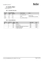
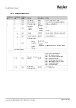
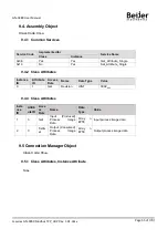
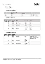
Summary of Contents for GN-9289

Page 1: ...Page 1 of 70 G series GN 9289 Modbus TCP_UDP Rev 1 01 docx Modbus TCP UDP network adapter GN 9289 User manual...

Page 2: ...GN 9289 User Manual Page 2 of 70 G series GN 9289 Modbus TCP_UDP Rev 1 01 docx DOCUMENT CHANGE SUMMARY REV PAGES REMARKS DATE Editor 1 00 New Document 2018 7 30 1 01 First release 2019 01 29 NJL...

Page 3: ...ACTIVE 12 2 3 5 Field Power Status LED 12 3 Dimension 13 3 1 GN 9289 13 4 Mechanical Set Up 14 4 1 Total Expansion 14 4 2 Plugging and Removal of the Components 14 4 3 Module mounting 15 4 4 How to s...

Page 4: ...2 5 5 0x05 Write Single Coil 37 8 2 6 6 0x06 Write Single Register 38 8 2 7 8 0x08 Diagnostics 39 8 2 8 15 0x0F Write Multiple Coils 41 8 2 9 16 0x10 Write Multiple Registers 42 8 2 10 23 0x17 Read Wr...

Page 5: ...Class Attributes Instance Attribute 55 9 6 Port Object 56 9 6 1 Common Services 56 9 6 2 Class Attributes 56 9 6 3 Instance Attributes 56 9 7 TCP IP Object 57 9 7 1 Common Services 57 9 7 2 Class Attr...

Page 6: ...assemble the products and wire with power applied to the system Else it may cause an electric arc which can result into unexpected and potentially dangerous action by field devices Arching is explosio...

Page 7: ...al for successful application and understanding of the product Identifiesinformation about practices or circumstances that can lead to personal injury property damage or economic loss Attentions help...

Page 8: ...ace 2 1 1 GN 9289 MODBUS TCP System power and Field power must be supplied separately Pin No Signal Description Signal Description Pin No 0 System Power 24V System Power Ground 1 2 System Power 24V Sy...

Page 9: ...Field Power Supply voltage 24Vdc typical Max 32Vdc Field Power Range is different depending on IO Module series Refer to IO Module s Specification Max Current Field Power Contact DC 10A Max Weight 16...

Page 10: ...rface Connector RJ 45 socket 2pcs IP Address Setup Via DHCP BOOTP or IOGuide Crevis Software IP Address Range xxx xxx xxx 1 253 User area xxx xxx xxx 254 255 Reserved for IAP Function Serial Port RS23...

Page 11: ...ower is supplied to the unit Device Operational Green The unit is operating in normal condition Device in Standby FlashingGreen The device needs commissioning due to configuration missing incomplete o...

Page 12: ...ngRed Adapter has no expansion module Internal Bus Connection Run Exchanging I O Green Exchanging I O data Expansion Configuration Failed Red One or more expansion module occurred in fault state Detec...

Page 13: ...GN 9289 User Manual Page 13 of 70 G series GN 9289 Modbus TCP_UDP Rev 1 01 docx 3 Dimension 3 1 GN 9289 mm...

Page 14: ...excepted to calculate maximum length because that is double width module 4 2 Plugging and Removal of the Components As above figure in order to safeguard the FnIO module from jamming it should be fix...

Page 15: ...GN 9289 User Manual Page 15 of 70 G series GN 9289 Modbus TCP_UDP Rev 1 01 docx 4 3 Module mounting...

Page 16: ...power RTB before wiring Current capacity margin should be considered when you supply the power Supply voltage 24Vdc which is recommendedvoltage level System and Field power must be supplied separately...

Page 17: ...GN 9289 User Manual Page 17 of 70 G series GN 9289 Modbus TCP_UDP Rev 1 01 docx 5 Convenience Function 5 1 Web Server Network Adapter...

Page 18: ...GN 9289 User Manual Page 18 of 70 G series GN 9289 Modbus TCP_UDP Rev 1 01 docx Expansion Module...

Page 19: ...ocx 5 2 IAP Functionality After setting up the dip switch as 254 or 255 Power off and on in order to start the IAP mode 254 Fixed IP Address 192 168 0 100 255 Last used IP Address After Login the Web...

Page 20: ...GN 9289 User Manual Page 20 of 70 G series GN 9289 Modbus TCP_UDP Rev 1 01 docx Has been updated Please reboot the adapter...

Page 21: ...t 0 Lowest IP Address when Pole 10 ON ex XXX XXX XXX IP_DIP 2 IP_DIP bit 1 3 IP_DIP bit 2 4 IP_DIP bit 3 5 IP_DIP bit 4 6 IP_DIP bit 5 7 IP_DIP bit 6 8 IP_DIP bit 7 9 ON Enable DHCP BOOTP 10 ON Use Lo...

Page 22: ...er Manual Page 22 of 70 G series GN 9289 Modbus TCP_UDP Rev 1 01 docx 6 3 RS232 Port for MODBUS RTU Touch Panel or IOGuide Pin Signal Name Description 1 Reserved 2 TXD RS232 TXD 3 RXD RS232 RXD 4 GND...

Page 23: ...r If the adapter BOOTP DHCP enabled DIP Pole 9 ON the adapter sends BOOTP DHCP request message of 20 times every 2sec If BOOTP DHCP sever does not response the Adapter applies its IP Address with EEPR...

Page 24: ...cx 6 4 2 IP Address Setup using DIP switch Manual function If the adapter DIP Pole 10 is ON lowest IP address is set by DIP Pole 1 8 manually These are examples of adapter IP Address setup by manual f...

Page 25: ...using BOOTP server Download BootPServerVerxxxx_Beijer from Beijer hompage Click Start Bootp to enable Bootp server to detect Bootp request on the network If the adapter is Bootp DHCP enabled Dip Pole...

Page 26: ...v 1 01 docx Double click on one of the detected Bootp request message and set the IP address If you wait for more the 40 seconds you have to restart the GN 9289 Another way to set are Add New Device C...

Page 27: ...GN 9289 User Manual Page 27 of 70 G series GN 9289 Modbus TCP_UDP Rev 1 01 docx Check IP address of the normal...

Page 28: ...n module may have 3 types of data as I O data configurationparameter and memory register The data exchange between network adapter and expansion modules is done via an I O process image data by G Seri...

Page 29: ...l register 3 4 6 16 23 0x1100 Read Write Adapter Informationspecial registers 3 4 6 16 23 0x2000 Read Write Expansion Slot Information special registers 3 4 6 16 23 The special register map must be ac...

Page 30: ...ow byte Slot 3 0x0003 Analog Input Ch1 high byte Slot 3 Analog Input Ch1 low byte Slot 3 0x0004 Analog Input Ch2 high byte Slot 3 Analog Input Ch2 low byte Slot 3 0x0005 Analog Input Ch3 high byte Slo...

Page 31: ...ut Ch3 high byte Slot 3 Analog Output Ch3 low byte Slot 3 0x0805 Empty Don t Care Discrete Out 4 pts Slot 5 Empty Don t Care Discrete Out 4 pts Slot 4 0x0806 Discrete Output low 8 pts Slot 7 Discrete...

Page 32: ...nd units All MODBUS requests and responses are designed in such a way that the recipient can verify that a message is finished For function codes where the MODBUS PDU has a fixed length the function c...

Page 33: ...zed by the client Request Initialized by the server Response Unit Identifier 1byte Identification of a remote slave connected on a serial line or on other buses Initialized by the client Recopied by t...

Page 34: ...number of output words Refer to MODBUS APPLICATION PROTOCOL SPECIFICATION V1 1a 8 2 1 1 0x01 Read Coils This function code is used to read from 1 to 2000 contiguous status of coils in a remote device...

Page 35: ...iscrete Inputs are addressed starting at zero Therefore Discrete inputs numbered 1 16 are addressed as 0 15 The discrete inputs in the response message are packed as one input per bit of the data fiel...

Page 36: ...ytes per register with the binary contents right justified within each byte For each register the first byte contains the high order bits and the second contains the low order bits Request Field name...

Page 37: ...x02 Response Field name Example Function Code 0x03 Byte Count 0x04 Input Register 0 Hi 0x00 Input Register 0 Lo 0x80 Input Register 1 Hi 0x00 Input Register 1 Lo 0x00 In case of address 0x0000 0x0001...

Page 38: ...mal response is an echo of the request returned after the register contents have been written Request Field name Example Function Code 0x06 Register Address Hi 0x08 Register Address Lo 0x00 Register V...

Page 39: ...b FunctionLo 0x00 Data Hi 0x11 Data Lo 0x22 Sub function 0x0000 0 Return Query Data The data passed in the request data field is to be returned looped back in the response The entire response message...

Page 40: ...2 0x0000 CRC Error Count Sub function 0x000D 13 Return Bus Exception Error Count The response data field returns the quantity of MODBUS exception responses returned by the remote device since its last...

Page 41: ...coil in a sequence of coils to either ON or OFF in a remote device The Request PDU specifies the coil references to be forced Coils are addressed starting at zero A logical 1 in a bit position of the...

Page 42: ...n code starting address and quantity of registers written Request Field name Example Function Code 0x0F Starting Address Hi 0x10 Starting Address Lo 0x08 Quantity of Registers Hi 0x00 Quantity of Regi...

Page 43: ...ata from the group of registers that were read The byte count field specifies the quantity of bytes to follow in the read data field Request Field name Example Function Code 0x17 Read Starting Address...

Page 44: ...server or slave was attemptingto perform the requested action 05 Acknowledge The server or slave has accepted the request and is processing it but a long duration of time will be required to do so 06...

Page 45: ...e Product name string ASCII GN 9289 Modbus TCPAdapter GBUS 0x1006 4102 Read 1word Sum check of EEPROM 0x1010 4112 Read 2word Firmware release date 0x1011 4113 Read 2word Product manufacturinginspectio...

Page 46: ...Setting Method 0 BOOTP 1 DHCP 0x1046 4166 Reserved 0x1047 4167 Read 1word Status of DIP SW 9 DHCP BOOTP Enable Disable 0 OFF 1 ON 0x1048 4168 Read 1word Enable disableLowest IP address via DIP Switch...

Page 47: ...ize of output image bit 0x110A 4362 Read 1word Update time for cyclic data change same as 0x1028 0x110D 4365 Read 1word Current Dip Switch State and Field Power Status MSB ex DHCP Booth enable Dip SW...

Page 48: ...t 12 0x2160 8544 0x217F 8575 Slot 13 0x2180 8576 0x219F 8607 Slot 14 0x21A0 8608 0x21BF 8639 Slot 15 0x21C0 8640 0x21DF 8671 Slot 16 0x21E0 8672 0x21FF 8703 Slot 17 0x2200 8704 0x221F 8735 Slot 18 0x2...

Page 49: ...x202D 8237 0x204D 8269 0x206D 8301 0x27CD 10189 0x0E 14 0x200E 8206 0x202E 8238 0x204E 8270 0x206E 8302 0x27CE 10190 0x0F 15 0x200F 8207 0x202F 8239 0x204F 8271 0x206F 8303 0x27CF 10191 0x10 16 0x2010...

Page 50: ...rd Read write output data this slot 0x0E 14 Read 1word GT number if GT 1238 returns 0x1238 0x0F 15 Read String upto 72byte First 1word is length of valid character string If GT 1238 returns 00 1E 52 5...

Page 51: ...ents are addressed by uniform addressing scheme consisting of Media Access Control Identifier MAC ID an integer identification value assigned to each node on a CIP network Class Identifier Class ID an...

Page 52: ...s Instance 0x01 Yes Yes Get_Attribute_All 0x05 No Yes Reset 0 Reset Only 1 Reset and Factory Default 0x0E No Yes Get_Attribute_Single 9 2 2 Class Attributes Instance ID Attribute ID Acces s Rule Name...

Page 53: ...ucture of USINT USINT 9 255 5 Get Status WORD Device status Defined in standard 6 Get Serial Number UDINT Unique Number 7 Get Product Name String Length ASCII String Short_Strin g USINT STRING 4DEC 92...

Page 54: ...Rule Name Data Type Value 0 1 Get Revision UINT 0001HEX 4 Get Number of Attribute UINT 0000HEX 5 Number of Service UINT 0000HEX 6 Get Maximum ID Number Class Attributes UINT 0000HEX 7 Get Maximum ID...

Page 55: ...e 9 4 2 Class Attributes Instance ID Attribute ID Access Rule Name Data Type Value 0 1 Get Revision UINT 0002HEX 9 4 3 Class Attributes Insta nce ID Attrib ute ID Acce ss Rule Name Data Type Value 1 3...

Page 56: ...e Name Data Type Value 0 1 Get Revision UINT 0001HEX 2 Get Max Instance UINT 0001HEX 3 Get Num Instances UINT 0001HEX 8 Get Entry Port UINT 0001HEX 9 Get All Ports ARRAY of STRUCT UINT UINT 0000HEX 00...

Page 57: ...ta Type Value 0 1 Get Revision UINT 0001HEX 2 Get Max Instance UINT 0001HEX 3 Get Num Instances UINT 9 7 3 Instance Attributes Instance ID Attribute ID Access Rule Name Data Type Value 1 1 Get Status...

Page 58: ...DIP switch 3 15 Reserved 4 Indicates pending configurationchange in TTL and or Mcast config 5 31 Reserved 9 7 3 2 Configuration Control Instance Attributes This attribute is a bitmap to control networ...

Page 59: ...X 9 8 1 Common Services Service Code Implemented for ServiceName Class Instance 0x01 Yes Yes Get_Attribute_All 0x0E Yes Yes Get_Attribute_Single 9 8 2 Class Attributes Instance ID Attribute ID Access...

Page 60: ...ID Attribute ID Access Rule Name Data Type Value 1 1 Get Interface Speed UDINT 10DEC 100DEC 2 Get Interface Flags DWORD Bit 0 Link Active Bit 1 Full Duplex Bit 2 4 Auto negotiation Bit 5 Manual Setti...

Page 61: ...Set Selection of Input Produced Process Image Mode USINT default 2 Fixed 6 Get Set Selection of Output Consumed Process Image Mode USINT default 0 Fixed 10 Get G Bus Status USINT 0 Normal Operation 1...

Page 62: ...s TCP_UDP Rev 1 01 docx External IDs Expansion Module ID Word Description 0 Network Adapter Module External ID 0x00 1 External ID for slot position 1 2 External ID for slot position 2 62 External ID f...

Page 63: ...e Offset Bit Offset Structure of USINT USINT Byte offset in the Input Assembly Corresponding bit offset in the byte If Input data length is zero then return Empty 4 Get Output Offset Table Byte Offset...

Page 64: ...1 0 Priority 2 usually it is used by Analog I O module 1 1 Priority 3 high S Status for Profibus Slot Diagnostic 0 No Status 1 Support Word Input Diagnostic 0x8000 32678 Input output Type 0 0 No I O...

Page 65: ...1 Bit 0 2 Data_Type Data_Length Output Information 3 Data_Type Data_Length Input Information MODBUS Reference MODBUS Reference Documents http www modbus org MODBUS Tools http www modbustools com MODBU...

Page 66: ...e powered Check main power Cable IOS LED flashes red Adapter has no expansion module Add one or more expansion modules IOS LED is red One or more expansion module occurred in fault state Detected inva...

Page 67: ...0RTB 2618 16 GT 2628 8 Points Source 24Vdc 2A 10RTB 2628 17 GT 2734 4 Points MOS Relay 240Vdc ac 0 5A 10RTB 2734 18 GT 2744 4 Points Relay 24Vdc 2A 240Vac 2A 10RTB 2744 19 GT 2764 4 Points MOS Relay 2...

Page 68: ...T 4154 4CH 0 20mA 16Bits 10RTB 4154 53 GT 4118 8CH 0 20mA 12Bits 10RTB 4118 54 GT 4158 8CH 0 20mA 16Bits 10RTB 4158 55 GT 4424 4CH 0 10Vdc 12Bits 10RTB 4424 56 GT 4464 4CH 0 10Vdc 16Bits 10RTB 4464 57...

Page 69: ...power for starting up CPU Field Power The power for input and output line Terminator Resistor Resistor for prevention reflected wave EDS Electronic Data Sheet Sink The method of in output powersupply...

Page 70: ...GN 9289 User Manual Page 70 of 70 G series GN 9289 Modbus TCP_UDP Rev 1 01 docx Head office Beijer Electronics AB Box 426 20124 Malm Sweden Phone 46 40 358600 www beijerelectronics com...

Reviews: