ENGLISH
U-CONTROL UMX490/UMX610 User Manual
8
ENGLISH
U-CONTROL UMX490/UMX610 User Manual
9
ASSIGN mode
4.2
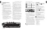
As already mentioned in previous chapters, the ASSIGN
Mode is a powerful tool to optionally reconfigure the UMX
into an ultra-comfortable controller.
The basic logic of the allocation process has been introduced
to you in Chapter 3 “Control elements and connections”. In
the following we will offer you more detailed information to
enable you to use the UMX even more efficiently.
Setting the GLOBAL CHANNEL
4.2.1
The UMX recognizes two separate classifications in regard to
MIDI channels. There is a GLOBAL CHANNEL and 16 SINGLE
CHANNELs.
The GLOBAL MIDI CHANNEL is the channel through which
all MIDI commands are sent in the factory setting: messages
by various control elements, as well as the Note On and Note
Off commands. To change this channel, proceed as follows:
Press the ASSIGN button and
1)
hold it down.
Press the
2)
CH SELECT
key.
Release the ASSIGN push-button.
3)
Define the GLOBAL CHANNEL by operating one of the
4)
keys
CH 1
through
CH 16
on the keyboard.
Finally, press the
5)
ENTER key. In order to discard your
assignments, please press the CANCEL key or press the
ASSIGN push-button again. The ASSIGN LED will go off in
all 3 cases.
The factory setting for the GLOBAL CHANNEL is channel 1.
◊
Individual channel assignment
4.2.2
The assignment of individual control elements to defined
channels is useful if you want to control several external
devices independently from each other.
Example:
You are playing synthesizer A through channel 2 with
the keyboard and have a sequencer program controlling
another synthesizer B through channel 5. You can now
control the filter frequency of device B through one of the
eight jog/shuttle controls in real time and simultaneously
continue to play device A without changing the filter
frequency.
Press the ASSIGN push-button and
1)
hold it down.
Activate the control element, for which another channel
2)
than the GLOBAL CHANNEL is to be set. If this is a
controller or fader, briefly move the control element;
when you have decided on a push-button, press this
push-button once. The UMX now “knows” which control
element you would like to assign to a
SINGLE CHANNEL
.
Release the ASSIGN push-button.
3)
Press one of the 16 channel keys
4)
CH 1
through
CH 16
.
Finally, press the
5)
ENTER key. In order to discard your
assignments, please select the CANCEL key or press the
ASSIGN push-button again. The ASSIGN LED will go off in
all 3 cases.
All control elements of the UMX follow the GLOBAL
◊
CHANNEL in their channel settings (factory settings).
This means that a control element is
always
in the
GLOBAL CHANNEL until you assign it to another channel.
Please also consider this when you change the GLOBAL
CHANNEL, since various elements will also change
accordingly!
GLOBAL CHANNEL assignment
4.2.3
Press the ASSIGN push-button and
1)
hold it down.
Activate the control element for which the GLOBAL
2)
CHANNEL is to be set. If this is a controller or fader, briefly
move the control element; when you have decided on
a push-button, press this push-button once. The UMX
now “knows” to which control element you would like to
assign a GLOBAL CHANNEL.
Release the ASSIGN push-button.
3)
Press the
4)
GLOBAL
key.
Finally, press the
5)
ENTER key. In order to discard your
assignments, please press the CANCEL key or press the
ASSIGN push-button again. The ASSIGN LED will go off in
all 3 cases.
The PANIC key combination
4.2.4
Imagine that you have been working continuously on one
song for several hours and a note suddenly “hangs up”. If you
now execute a PANIC command, a sound producing device
receiving this command becomes silent immediately.
Press the ASSIGN push-button and
1)
hold it down.
Press one of the two PANIC keys,
2)
RESET ALL
or
NOTES OFF
.
Release the ASSIGN push-button. The device will
3)
automatically return to the normal play mode.
The command “All Notes Off” will be sent immediately
◊
after you have pressed one of the two keys.
The SNAPSHOT SEND command
4.2.5
The SNAPSHOT command triggers the transmission of
all parameters including their current values. All control
element assignments as well as their temporary settings on
the respective channels are transmitted to the MIDI OUT
socket and to the USB output of the UMX.
It is possible by this method to transfer the complete UMX
mapping to a sequencer software at the beginning of a
song. This is to make sure the song is played with the last
valid controller values. Apart from this, the SNAPSHOT allows
you to reset the correct values in an external device where
parameters have shifted.
Press the ASSIGN push-button and
1)
hold it down.
Press the
2)
SNAP SEND
key on the keyboard.
Release the ASSIGN push-button. The device
3)
automatically returns to the normal play mode.
The SNAPSHOT command is transmitted immediately
◊
after activating the keyboard.
Local Off
4.2.6
The LOCAL OFF in the UMX has the effect that value entries
made via the control elements are neither transmitted to the
MIDI OUT socket nor to the USB OUT. It is therefore possible
in the LOCAL OFF mode, for example, to read just the rotary
controls without transmitting data to the generally selected
external devices.
Press the ASSIGN push-button and
1)
hold it down.
Press the
2)
LOCAL OFF
key.
Release the ASSIGN push-button again and complete the
3)
desired settings on the control elements.
Then, press the
4)
ENTER key or the CANCEL key. The LED
of the ASSIGN key goes off in both cases and you are in
normal play mode again.
Control elements assignment
4.2.7
We explained in Chapter 4.2.2 how an individual channel can
be assigned to each control element. You will now find out
how to assign new controllers and a channel.
The assignment for rotary controls R1 – R8, the
a)
MODULATION controller, the PITCH BEND wheel, as
well as the DATA fader.
1) Press the ASSIGN push-button and hold it down.
2a) If you would like to assign one of the eight rotary
controls, turn the respective controller.
2b) If you assign the MODULATION controller,
please activate one of the keys located below the
lettering
MOD WHEEL ASSIGN
,
MODULA
,
VOLUME
or
CC
. You can bypass step 5, if you decide on the
MODULA
or the
VOLUME
key. The MIDI controller
“MODULATION” (CC 1) or “CHANNEL VOLUME”
(CC 7) is then directly assigned to the MODULATION
controller without having to enter a controller
number first.
2c) If you assign the PITCH BEND wheel, please
activate one of the keys located below the lettering
PB WHEEL ASSIGN
,
PITCH BEND
or
CC
. You can
bypass step 5, if you decide on the
PITCH BEND
key. The
original pitch bend function is then directly assigned
to the PITCH BEND wheel.
2d) If you complete an assignment for the DATA fader,
please activate one of the keys located below the
lettering
SLIDER ASSIGN
,
VOLUME
or
CC
. You
can bypass step 5 if you decide on the
VOLUME
key.
The original volume function is then directly assigned
to the DATA fader.
3) Release the ASSIGN push-button again.
4) Press one of the 16 channel push-buttons
CH 1
through
CH 16
to define the channel.
5) Press the number keys on the keyboard in sequence
until you have completely entered the desired
controller number. Only value entries between 0 and
127 are possible. Greater values are ignored by the
device.
Examples:
- Press keys
1
and
4
if you have decided on
CC 14, for example.
- Press keys
1
,
0
and
7
if you would
like to select CC 107.
6) Finally press the ENTER key. In order to discard
your assignments, please press the CANCEL key or
press the ASSIGN push-button again. The LED of the
ASSIGN push button will go off in all 3 cases.
Assigning push-buttons B1 – B8 and the optional
b)
sustain pedal connected to the socket
15
.
1) Press the ASSIGN push-button and hold it down.
2) Press the related control element once (however, it is
not necessary to continue pressing it).
3) Release the ASSIGN push-button again.
4) Press one of the 16 channel push-buttons
CH 1
through
CH 16
to define the channel.
5) Press the number keys on the keyboard in sequence
until you have completely entered the desired
controller number. Only value entries between 0 and
127 are possible. Greater values are ignored by the
device.
6) Finally, press the ENTER key. In order to discard
your assignments, please press the CANCEL key or
press the ASSIGN push-button again. The LED of the
ASSIGN push button will go off in all 3 cases.
Please note two exceptions in conjunction with the push-
buttons and/or the sustain pedal.
If you assign CC 07 (Channel Volume) to the push-buttons,
◊
a channel volume of 0 is triggered each time you press the
push-button. This means the channel is always mute. This
feature is very useful for live operation.
If you use controller CC 10 (panning) for the push-buttons
◊
or the sustain pedal, pressing the control element
transmits value 64. This results in hearing the content of
the channel in the center of the stereo panorama.


