5
MINIFBQ FBQ800 User Manual
2.2 Front panel
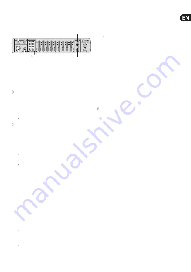
This section describes how to use the front panel of the FBQ800,
illustrated as follows:
(4)
(3) (5)
(7) (1)
(2)
(8)
(6)
(9)
Fig. 2.1: FBQ800 front panel
In the previous illustration, each control element is associated with a
callout, for example . To identify details about each control element
in this documentation, use these callouts. The numeric order of these
callouts identifies the FBQ800 signal path.
◊
Before you turn on the FBQ800, turn the LEVEL control to -12
(minimum setting).
(1)
�
(
POWER
) button: To turn the FBQ800 on and off, use this
button, which can appear:
•
pushed in and illuminated: The FBQ800 is on.
•
not pushed in and not illuminated: The FBQ800 is off.
◊
When you finish using the FBQ800, unplug the power supply
unit from the power source. As long as the power supply
unit is connected to a power source, the power supply unit
consumes energy.
(2)
IN/OUT
button: To activate or, alternatively deactivate control
elements, use this button, which can appear:
•
pushed in and illuminated: The FBQ800 activates all
control elements.
•
not pushed in and not illuminated: The FBQ800
deactivates most control elements. However, you can use
the METER SELECT button
(5)
and the IN/OUT meter
(6)
.
If you activated all control elements
(2)
, you can use control elements
(3)
and
(4)
to prepare the input signal for EQing, as follows:
(3)
LEVEL CONTROL
: To adjust the level of the input signal, turn
this control toward
-12 dB
(minimum setting) or, alternatively
+12 dB
(maximum setting). Some signals have high levels that
can deteriorate sound and equipment.
For details about managing the signal level, see
(6)
How to
manage the signal level
.
(4)
LOW CUT
button: To manage the low-cut filter, use this button,
which can appear:
•
pushed in and illuminated: The low-cut filter eliminates
sounds that are below 75 Hz (floor rumble, room
resonance, and mains hum, for example).
•
not pushed in and not illuminated: The low-cut filter does
not eliminate any sounds.
To monitor the input signal or, alternatively the output signal,
use control elements
(5)
and
(6)
, as follows:
(5)
METER SELECT
button: To select the type of signal you want to
monitor, use this button, which can appear:
•
pushed in and illuminated: Monitor the
input
signal as
soon as this signal enters the FBQ800. The FBQ800 does
not apply the LEVEL control or any other control elements
to the input signal that you monitor.
•
not pushed in and not illuminated: Monitor the
output
signal as soon as this signal leaves the FBQ800.
The FBQ800 applies all control elements to the output
signal that you monitor. However, if you deactivated most
of the control elements
(2)
, the input signal and the
output signal are the same.
(6)
IN/OUT METER
: To monitor the level of the signal that you
selected with the METER SELECT button, use this stereo meter.
Both the left (
L
) and right (
R
) sides of this meter share the same
decibel scale (
-24 dB
to
+6 dB
). If the signal level is too high,
the CLIP LED illuminates.
◊
At 0 (zero) dB, the FBQ800 still has approximately 15 dB of
headroom. How to manage the signal level
Optimally, you want to maintain the signal level of the FBQ800
at 0 dB. When the signal level is:
•
less than 0 dB, the signal is not full. If the difference
between the level of the noise floor and the level of the
signal is not sufficient, you lose signal quality.
•
greater than 0 dB, the CLIP LED illuminates on the
IN/OUT meter. The signal can overload the FBQ800.
However, occasional clipping will not damage the
sound quality.
Because sounds are not perfectly consistent, you cannot flawlessly
maintain the signal level at 0 dB. However, you can consistently
manage the signal level. This involves monitoring and adjusting the
level of the input signal and the output signal, as follows:
1.
To begin EQing in a neutral environment, set all frequency-band
faders
(9)
to 0 dB.
2.
To protect the FBQ800 against signals that are unexpectedly
high, turn the LEVEL control
(3)
to -12 dB.
3.
To monitor the input level, use the METER SELECT button
(5)
together with the IN/OUT meter
(6)
, as described in this
documentation. If the input level is higher or lower than 0 dB
and you:
•
can adjust the output level of the input source, adjust the
output level of the input source
until the
input level
of the FBQ800
is 0 dB
•
cannot adjust the output level of the input source, set the
output level of the FBQ800 to 0 dB, as follows:
A.
To activate all control elements, use the IN/OUT
button
(2)
.


