background image

8. Checking to see if front weights need to be added to the tractor in order to maintain

balance.

9. Checking the tractor tires for the proper pressure in accordance with the tractor

operator’s manual.

10. Making sure the proper attire is worn. Avoiding loose fitting clothing which can

become entangled. Wearing sturdy, tough-soled work shoes and protective
equipment for eyes, hands, ears and head. Never operate tractor or implements in
bare feet, sandals or sneakers.

11. Checking area for stones, branches and other debris that might be thrown.
12. Ensuring proper lighting is available, sunlight or good artificial lighting.

3.07 - Working Speed

Ground speed is determined by the soil condition and tractor power. Simple
experimentation will determine the best speed for the desired results, usually 8 to 14
mph. 

3.08 - Operating Techniques

When working, rake wheels should slightly touch the ground. This gives the individual
wheels and tines maximum flexibility to insure clean raking on any terrain. The correct
pressure will always depend on field conditions, quantity and type of forage being
windrowed. For heavy crops, more down pressure may be needed. Too much pressure
may cause dirt and debris to be rolled into the windrow. The ideal setting allows rake to
float smoothly across ground contour while moving crop cleanly into a row.
If the crop was mowed with a sickle bar mower, operate the rake in the same direction
the crop was mowed, while if the crop was mowed with a rotary mower, best results are
obtained by operating the rake in the opposite direction the crop was mowed.

To set ground pressure do the following:
1. Slide the lock plate

 (see fig. 5)

 in the unlocked position and secure it with the Ø5

hairpin cotter. This will allow the rake to float evenly across the surface even when
raking over uneven terrain and prolong the life of the rake’s teeth.

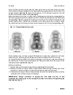
2. Lower rake so that wheels are slightly touching the ground. Adjust the tractor’s lift

arms so that they are approximately 19” from the ground when raking 

(see fig. 7)

and 22” from the ground when spreading or turning the hay

 (see fig. 8 and 9)

.

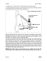
3. Assemble the spring clip in the desired position. The pressure that the rake wheel

applies on the ground can be adjusted by bolting the lower spring clip to one of the
other two holes available on the pivot housing tube 

(see fig. 5)

. Moving the lower

spring clip to one of the holes further away from the springs will cause the spring
tension to increase and therefore decrease the amount of pressure that the rake
wheels will apply on the ground. As a general rule, in standard working conditions
use the first hole for RS2-04 rakes 

(see #1, fig. 5)

 and the second hole for RS2-05

and RS2-06 rakes 

(see #2, fig. 5)

. Setting the rake with the least amount of

pressure will help to keep the finger wheels cleaner and therefore keep dirt off the
forage.

O

PERATION

15

BEFCO

H

AY

 R

AKES

O

PERATOR

S

 M

ANUAL

Summary of Contents for RS2-04L

Page 1: ...perator s Manual HAY EQUIPMENT Hay Rakes RS2 04R RS2 05R RS2 06R RS2 04L RS2 05L RS2 06L The operator s manual is a technical service guide and must always accompany the machine Manual 960 184B Novemb...

Page 2: ...r each have been selected using the following guidelines DANGER Indicates an imminently hazardous situation that if not avoided will result in death or serious injury WARNING Indicates a potentially h...

Page 3: ...19 3 09 Uneven Terrain 15 3 08 Operating Techniques 15 3 07 Working Speed 14 3 06 Startup 13 3 05 Attaching to the Tractor 13 3 04 Pre Operational Check 11 3 03 Assembly Instructions 11 3 02 Setup 9...

Page 4: ...tations of this warranty Warranty is provided for customers who operate and maintain their equipment as described in this manual Warranty registration is accomplished by the dealer by completing and f...

Page 5: ...te showing the model and the serial number Record your implement model and serial number in the space provided below Your dealer needs this information to give you prompt efficient service when you or...

Page 6: ...s and is instructed in safe and proper use 2 01 Preparation 1 Before operating equipment read and understand the operator s manual and the safety signs see fig 2 2 Thoroughly inspect the implement bef...

Page 7: ...Signs 1 Read and adhere to all safety and operating decals on this machine see fig 2 2 Before dismounting tractor Allow moving parts to stop stop engine set brake and remove the key of unattended equi...

Page 8: ...Fig 2 Safety decals implement replace immediately if damaged SAFETY PRECAUTIONS 8 BEFCO HAY RAKES OPERATOR S MANUAL right side left side...

Page 9: ...rk safety aside from the features on our hay rakes are very much due to the responsible use of the equipment It must always be operated prudently following with great care the safety instructions laid...

Page 10: ...re beginning operation contact local utility companies to make certain there are no bundled gas lines electrical cables etc in the work area 17 Reduce speed on slopes and sharp turns to minimize tippi...

Page 11: ...found either on the machine or in the hardware bag Assembly will be easier if all parts are loosely assembled before tightening the hardware CAUTION Stand clear of bands when cutting as they could be...

Page 12: ...f the support arm and secure it using the M14x100 bolt the lock washer and the M14 nut Note When installing the arms with hubs always make sure to assemble them to the support arm with the bend facing...

Page 13: ...rappings or foreign objects are around the implement 2 The teeth are properly installed and the bolts properly torqued4 3 All hardware is tight 4 No people or animals are in the work area 3 05 Attachi...

Page 14: ...e point movement DANGER Never attempt to attach the implement to the tractor or make any adjustments to it without first turning the tractor off DANGER Failure to ensure a secure coupling of the imple...

Page 15: ...as mowed with a sickle bar mower operate the rake in the same direction the crop was mowed while if the crop was mowed with a rotary mower best results are obtained by operating the rake in the opposi...

Page 16: ...the ones used when operating a left hand rake Under normal working conditions it is advisable to select a hole position between 3 and 5 see fig 6 Remove the locking pin from the transport position hol...

Page 17: ...ee fig 7 Proper raking is obtained by positioning the bends on both the support arm and the arms with hubs towards the back of the unit OPERATION 17 BEFCO HAY RAKES OPERATOR S MANUAL Fig 6 Angling the...

Page 18: ...he support arm and the arms with hubs towards the tractor see fig 8 Turning models RS2 04 RS2 06 In the turning position each pair of rake wheels overlap front to back turning the forage crop and allo...

Page 19: ...ng Avoid sudden stops and starts and slow down before changing directions on a slope 4 Pass diagonally through sharp dips and avoid sharp drops to prevent hanging up the tractor and implement 5 Slow d...

Page 20: ...rance to raise the support arm of larger rakes to the 90 position and off the ground enough to transport them on the road On models RS2 05 and RS2 06 it will be necessary to turn the arm with hub furt...

Page 21: ...have come to a complete stop before attempting to perform maintenance 6 Never work under equipment unless it is blocked securely 7 Always use personal protection devices such as eye hand and hearing...

Page 22: ...eels Check for any loose teeth bolts or missing hardware 2 Replace any damaged or worn tooth Hourly or whenever an obstacle is hit 1 Check machine condition particularly the rake wheel teeth 2 Replace...

Page 23: ...2 152 206 97 131 2 M16 171 232 121 164 79 106 18 9 16 154 209 105 142 69 94 1 5 M14 154 208 109 147 70 95 12 9 16 144 195 98 133 62 84 2 M14 120 163 85 115 55 75 20 1 2 98 133 66 90 44 59 1 25 M12 106...

Page 24: ...ake teeth should be replaced when they are damaged have lost their original shape or when they are worn to a point that forage is not being raked properly anymore To replace individual teeth do the fo...

Page 25: ...areas indicated under Maintenance9 5 Apply a thin layer of grease to rake teeth to prevent them from rusting 6 Paint exposed metal to inhibit rusting 7 Replace any damaged or missing decals 8 Lower th...

Page 26: ...orrect ground speed Hay bunching Ensure tractor SCV lever is in float position while working Bolt lower spring clip to hole further away from springs to reduce ground pressure see fig 5 Excessive grou...

Page 27: ...itch Too much machine weight on teeth Raise rake before backing up Backing up with teeth on the ground Teeth bending Protect teeth from weather or treat with rust retardant Teeth have become corroded...

Page 28: ...heating of bearings Operator s Manual Review the Operator s Manual with the customer Explain the following Warranty Safe operation and service Correct machine installation and operation Daily and peri...

Page 29: ...h or performance of any warranty on the Company s Machine are those set forth herein In no event will the dealer the Company or any company affiliated with the Company be liable for a Injuries or dama...

Page 30: ...s shop It is assumed that the dealer has the appropriate general and special tools to service the machine Time required for replacement of knives oil grease and to remove excessive dirt from the Machi...

Page 31: ...arranty and understand clearly that there were and are no other representations of warranties either expressed or implied made by anyone I have been advised on proper operation maintenance and lubrica...

Page 32: ...Cut along this line Sender Fold here BEFCO Inc Warranty Department P O Box 6036 Rocky Mount NC 27802 6036 Place stamp here...

Page 33: ...CO Parts Manual HAY EQUIPMENT Hay Rakes RS2 04R RS2 05R RS2 06R RS2 04L RS2 05L RS2 06L Parts Manual 12 2013 RS2 04R 05R 06R Ver A RS2 04L 05L 06L Ver A BEFCO RS2 04 RS2 05 RS2 06 US lwp November 13 2...

Page 34: ...HAY RAKES THREE POINT HITCH OPERATOR S MANUAL RS2 04 RS2 05 RS2 06 PARTS MANUAL 34 BEFCO 08 2013...

Page 35: ...M14 2 00 C6 Z 003 0358 16 1 Bolt HH M12 1 75x120 C8 8 Z P 009 1301 15 1 Upper spring clip 502 935B 14 2 Spring frame holder hitch 502 936B 13 1 Lower spring clip 502 937B 12 1 Bolt HH M12 1 75x40 C8 8...

Page 36: ...HAY RAKES FRAME OPERATOR S MANUAL RS2 04 PARTS MANUAL 36 BEFCO 08 2013...

Page 37: ...8 Z F 000 7716 5 2 Hairpin cotter 3 001 5240 4 2 Pin locking 12x56 Z 502 938B 3 2 Arm w hub left 2 wheel RS2 04L 502 948B 2 Arm w hub right 2 wheel RS2 04R 502 947B 2 1 Support arm 4 wheel RS2 04 502...

Page 38: ...HAY RAKES FRAME OPERATOR S MANUAL RS2 05 PARTS MANUAL 38 BEFCO 08 2013...

Page 39: ...TK 000 1019 7 1 Washer lock 14 Z 000 1020 6 1 Bolt HH M14 2 00x100 C8 8 Z P 003 0285 5 2 Hairpin cotter 3 001 5240 4 1 Arm w hub 1 wheel RS2 05 502 954B 3 2 Arm w hub left 2 wheel RS2 05L 502 948B 2 A...

Page 40: ...HAY RAKES FRAME OPERATOR S MANUAL RS2 06 PARTS MANUAL 40 BEFCO 12 2013...

Page 41: ...irpin cotter 3 001 5240 4 3 Arm w hub left 2 wheel RS2 06L 502 948B 3 Arm w hub right 2 wheel RS2 06R 502 947B 3 1 Support arm 6 wheel rear section RS2 06 18031075 2 1 Support arm 6 wheel one piece RS...

Page 42: ...HAY RAKES RAKE WHEEL HUB OPERATOR S MANUAL RS2 02 RS2 03 RS2 04 RS2 05 RS2 06 PARTS MANUAL 42 BEFCO 08 2013...

Page 43: ...N 502 953B 12 1 Bearing 30204 502 224B 11 1 Bearing 30205 000 9771 10 1 Dust seal ring 502 218B 9 1 Hub rake wheel 502 223B 8 6 Washer ext lock 10 Z 003 5060 7 6 Nut HH M10 1 50 C6 Z MD 009 0150 6 20...

Page 44: ...HAY RAKES DECALS OPERATOR S MANUAL RS2 04 RS2 05 RS2 06 PARTS MANUAL 44 BEFCO 08 2013...

Page 45: ...0B 7 1 Decal RS2 950 477B 6 1 Decal CAUTION To avoid serious injury 950 417B 5 1 Decal WARNING Crushing hazard 950 493B 4 2 Decal B 950 226B 3 1 Decal BEFCO Inc address 950 381B 2 1 Decal BEFCO 950 10...

Page 46: ......
Page 47: ...tails in this manual without the expressed written permission of the Company Technical information provided in this manual is approximate the Company reserves the right to modify or improve the models...

Page 48: ...BEFCO RS2 04 RS2 05 RS2 06 US lwp Printed in the USA November 13 2014 P O Box 6036 Rocky Mount NC 27802 6036 Tel 252 977 9920 Fax 252 977 9718 www befco com...

Reviews: