AC/DC v1 - ASSEMBLY GUIDE
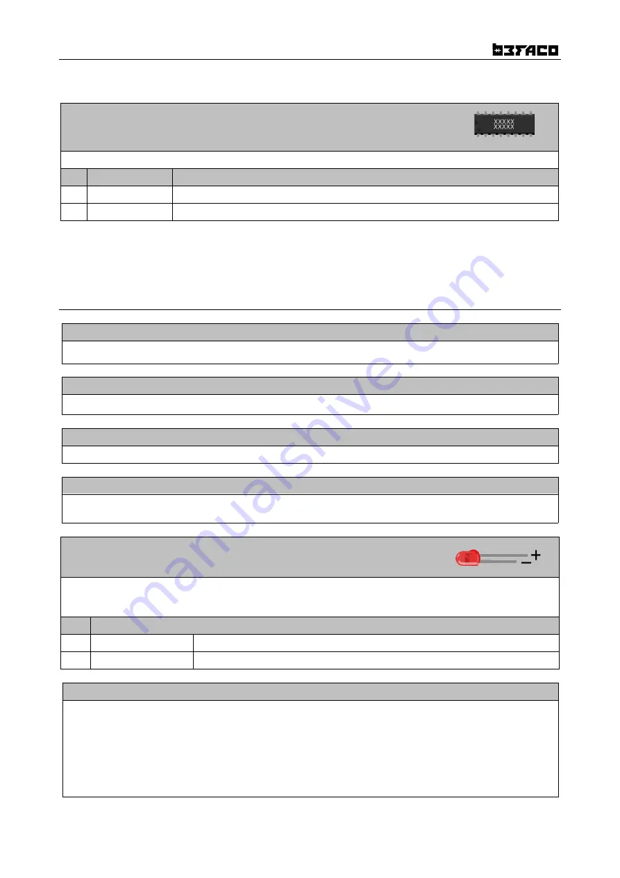
ICs
Place ICs in their sockets. Take care of polarity, notch or dot mark orientation.
Qty
Value
Name on PCB
1
TL072
IC1
4
NE5532
IC2, IC3,IC4,IC5
Now we will proceed to mount mechanical components. This part of the assembly is
CRITICAL
. Please take your time
and read the following instructions carefully.
These components must
NOT
be soldered until they are placed on the PCB and fully attached to the front panel.
OPEN MECHANICAL COMPONENTS BAG
SPACER
Secure the 11 mm. spacer into control PCB on the component side. Mind it will be screwed to the other PCB
USB CONNECTOR
Place USB connectors but
don't solder it yet.
MINIJACKS
Place mini-jacks on the PCB ensuring they are on the side with the silkscreen but
don't solder them.
POTS
Place pots but do not put them all the way in, as they might short components beneath. You need to cut one of the
location lugs so they will fit in.
Do not solder the pots yet!
LEDs
Place the LEDs onto the PCB minding their polarity, but
don't solder them
until the front panel is in place. This is
the only way to solder them in the right position.
The long leg is the positive and the short the negative. On the PCB the square pad indicates the negative side
Qty
Name on PCB
8
Green LED
L2, L4, L6, L8, L9, L10, L11, L12
4
Red LED
L1, L3, L5, L7
FRONT PANEL
Attach the
front panel
adjusting the parts one by one if necessary until they fit. First
Mini-jacks
then
POTS.
Use
the red nuts for Outs, the smaller black nuts for the rest of the minijacks and the larger black ones for all pots.
Ensuring all of the above parts are flush with the panel. MIND THE POTS! So they do not touch components beneath.
Solder Mini-jacks, USB and pots.
Flip the module and make sure that LEDs fall flat in their holes, then proceed to solder them.
TIP:
Leave pots location lugs unsoldered. Like this you will be able to reach under the pots in case of troubleshooting.
Connect both PCBs together, then use the remaining screw to secure them. Then proceed to put in place Xibeca board.
Connect power cable making sure its properly oriented.
5
Summary of Contents for AC/DC
Page 6: ...AC DC v1 ASSEMBLY GUIDE 6...


