Chapter 3
SPS.500 Wiring
20
Bedrock SPS.500 User Manual - BRDOC125_007
9/3/21
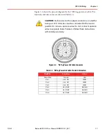
5 shows the pin out diagram for the relay cable. Pin functions and wire
colors are shown in Table 3
CAUTION:
See the Specifications appendix for relay contact
rating information.
Figure 3
-
5 Relay Cable Connector
Table 3
-
4 Relay Cable Pin Out Information
Pin/Wire
Function
Color
Pin 1
RELAYA (NC)
BLACK
Pin 2
RELAYA (COM)
RED
Pin 3
RELAYA (NO)
WHITE
Pin 4
RELAYB (NC)
GREEN
Pin 5
RELAYB (COM)
ORANGE
Pin 6
RELAYB (NO)
BLUE
Pin 7
Drain Wire
N/A
Pin 8
Not Connected
N/A


