background image

Mounting and wiring

KM2774

11

Version: 2.0.0

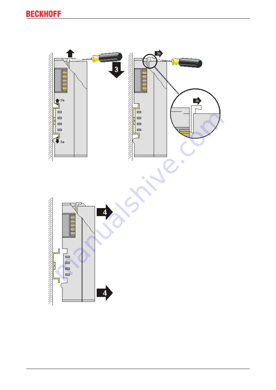
◦ an internal mechanism pulls the two latching lugs (3a) from the top hat rail back into the terminal

module,

◦ the unlatching hook moves forwards (3b) and engages


• In the case 32 and 64 channel terminal modules (KMxxx4 and KMxxx8 or EMxxx4 and EMxxx8) you

now lever the second unlatching hook on the right-hand side of the terminal module upwards in the
same way.

• Pull (4) the terminal module away from the mounting surface.

3.2

Recommended mounting rails

Terminal Modules und EtherCAT Modules of KMxxxx and EMxxxx series, same as the terminals of the
EL66xx and EL67xx series can be snapped onto the following recommended mounting rails:

• DIN Rail TH 35-7.5 with 1 mm material thickness (according to EN 60715)

• DIN Rail TH 35-15 with 1,5 mm material thickness

Summary of Contents for KM2774

Page 1: ...Documentation EN KM2774 Terminal module for jalousie motors 2021 03 03 Version 2 0 0...

Page 2: ......

Page 3: ...KS2000 Configuration Software 16 4 1 KS2000 Introduction 16 4 2 Parameterization with KS2000 17 4 3 Settings 18 5 Access from the user program 20 5 1 Process image 20 5 2 Mapping 21 5 3 Control and s...

Page 4: ...Table of contents KM2774 4 Version 2 0 0...

Page 5: ...tion of products that have already been supplied may be made on the basis of the data diagrams and descriptions in this documentation Trademarks Beckhoff TwinCAT EtherCAT EtherCAT G EtherCAT G10 Ether...

Page 6: ...ained specialists in control automation and drive engineering who are familiar with the applicable national standards Description of instructions In this documentation the following instructions are u...

Page 7: ...0 0 1E 04 The firmware and hardware version can be found in the serial number on the label at the bottom of the terminal module Syntax of the serial number Structure of the serial number WW YY FF HH W...

Page 8: ...20 mA e g for connecting a button LED are available for each motor The outputs are protected against overload An adjustable overcurrent limit protects the motor from damage LEDs indicate the status o...

Page 9: ...e 1 Signal voltage 1 15 V 30 V IEC 61132 2 type 1 Input filter 3 0 ms Input current typically 3 mA IEC 61132 2 type 1 Power supply for the electronics via the K bus Current consumption via K bus typic...

Page 10: ...should use flat mounting connections e g countersunk screws or blind rivets WARNING Risk of electric shock and damage of device Bring the bus terminal system into a safe powered down state before sta...

Page 11: ...lever the second unlatching hook on the right hand side of the terminal module upwards in the same way Pull 4 the terminal module away from the mounting surface 3 2 Recommended mounting rails Termina...

Page 12: ...state before starting mounting disassembly or wiring of the Bus Terminals Fig 2 KM2774 Wiring Connection for supply voltage 24 V CAUTION Ground the 0 V potentials of the 24 V supply voltage Connect t...

Page 13: ...24 V for push button 1 IN1 Channel 2 Input for button 1 2 IN2 Channel 2 Input for button 2 3 IN3 Channel 2 Input for button 3 4 LED Channel 2 Switched ground for button LED X3 Ch3 0 24 V Channel 3 24...

Page 14: ...l 2 Protective earth for motor 2 X13 Ch3 0 L1 Channel 3 Phase L1 for motor 3 1 L2 Channel 3 Phase L2 for motor 3 2 L3 Channel 3 Phase L3 for motor 3 3 N Channel 3 Neutral conductor for motor 3 interna...

Page 15: ...Mounting and wiring KM2774 15 Version 2 0 0 3 4 Dimensions Fig 3 KM2774 Dimensions...

Page 16: ...Box Modules can be prepared before the commissioning phase Later on this configuration can be transferred to the terminal station in the commissioning phase by means of a download For documentation p...

Page 17: ...in parallel with the actual fieldbus mode of the terminal station The fieldbus protocol always has the higher priority in this case 4 2 Parameterization with KS2000 Connect the configuration interface...

Page 18: ...the register of the KM2774 0000 The dialog screen for parameterizing the KM2774 0000 can be found under Settings 18 ProcData shows the process data of the KM2774 0000 4 3 Settings Settings for parame...

Page 19: ...nt limit is exceeded Dead time for channel 2 R39 R39 29 Here you can define the dead time until overcurrent shutdown for channel 2 default 400 ms Permissible value range 100 to 2560 ms in steps of 10...

Page 20: ...Coupler places values on even byte addresses Key SB Status byte not applicable for compact evaluation CB Control byte not applicable for compact evaluation DataIN Process input data DataOUT Process ou...

Page 21: ...es please refer to the pages Process image and Control and status byte Compact evaluation Under compact evaluation the KM2774 occupies addresses in the input and output process image Control and statu...

Page 22: ...ola format with word alignment Address Input data Output data Conditions Word offset High byte Low byte High byte Low byte Complex evaluation yes Motorola format yes Word alignment yes 0 reserved SB r...

Page 23: ...byte SB is located in the input image 20 and is transmitted from the terminal to the controller Bit SB 7 SB 6 SB 5 SB 4 SB 3 SB 2 SB 1 SB 0 Name RegAccess Error OverTemp Err230V Err24V Key Bit Name D...

Page 24: ...with input data word DataIn 20 or want to write with output data word DataOut 20 Status byte for register communication The status byte SB is located in the input image 20 and is transmitted from the...

Page 25: ...Current is lower than the switching threshold specified for channel 3 1bin Current is higher than the switching threshold specified for channel 3 10 Ch3 IN3 Channel 3 input 3 9 Ch3 IN2 Channel 3 input...

Page 26: ...output L2 12 Ch4 L1 Channel 4 output L1 11 Ch3 LED 0bin Ground for button LED is not connected 1bin Ground for button LED is connected 10 Ch3 L3 Channel 3 output L3 9 Ch3 L2 Channel 3 output L2 8 Ch3...

Page 27: ...Data structure 0x0004 4dec R ROM R14 reserved R15 Alignment register 0x7F80 32640 R W RAM R16 28 Hardware version number e g 0x0000 e g 0dec R W EEPROM R17 reserved R28 reserved R29 28 Terminal type s...

Page 28: ...1 corresponds to the ASCII character 1 0x41 corresponds to the ASCII character A This value cannot be changed R16 Hardware version number Register R16 contains the hardware version of the terminal R29...

Page 29: ...s off immediately when the current limit is exceeded R39 Dead time for overcurrent shutdown channel 2 Here you can define the dead time until overcurrent shutdown for channel 2 default 40dec Scaling 4...

Page 30: ...l byte as a receipt in the status byte The terminal returns the firmware version 0x3341 in the input data word byte 1 and byte 2 This is to be interpreted as an ASCII code ASCII code 0x33 represents t...

Page 31: ...switched on Bit 0 6 not set means reading the register Bits 0 5 to 0 0 specify the register number 31 with 01 1111bin The output data word byte 1 and byte 2 has no meaning during read access Input Da...

Page 32: ...Output Data Byte 0 Control byte Byte 1 DataOUT1 high byte Byte 2 DataOUT1 low byte 0xA0 1010 0000bin 0xXX 0xXX Explanation Bit 0 7 set means Register communication switched on Bit 0 6 not set means r...

Page 33: ...N1 high byte Byte 2 DataIN1 low byte 0x9F 1001 1111bin 0xXX 0xXX Explanation The terminal returns a value as a receipt in the status byte that differs only in bit 0 6 from the value of the control byt...

Page 34: ...ents there Beckhoff Support Support offers you comprehensive technical assistance helping you not only with the application of individual Beckhoff products but also with other wide ranging services su...

Page 35: ...outputs for four blind motors 8 Fig 2 KM2774 Wiring 12 Fig 3 KM2774 Dimensions 15 Fig 4 KS2000 configuration software 16 Fig 5 Display of the fieldbus station in KS2000 17 Fig 6 KS2000 branch for chan...

Page 36: ......

Page 37: ...Beckhoff Automation GmbH Co KG H lshorstweg 20 33415 Verl Germany Phone 49 5246 9630 info beckhoff com www beckhoff com...

Reviews: