KS2000 Configuration Software
KL8001 and KL9060
27
Version: 2.0.0
Registerdata
Enter the various threshold values here. The range of values for some of the input fields is restricted (e.g. the
rated current must be between 0.0 and 25.0 A), and is automatically limited during input.
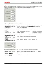
Fig. 19: Setting the register values; example: phase L1
Rated current
,
)
Default: 0 A
permitted setting range:
0.9 A to 15.0 A
Specification of the rated current for the L1, L2 and L3 phases.
These values are only used when both the
for setting the rated current are set to zero. Otherwise the value set with the rotary
switches applies to all three phases.
Switch-on threshold
,
)
Default: 0
Specification of the switch-on threshold for the L1, L2 and L3 phases.
Overvoltage*
,
)
Default: 350 V
Specifying the threshold value for overvoltage
for phases L1, L2 and L3.
*) The voltages of the three phases
are measured with reference to an
artificial star point.
Undervoltage*
,
)
Default: 150 V
Specifying the threshold value for undervoltage
for phases L1, L2 and L3.
Overload
,
)
Default: 25 A
Specification of the overload thresholds for the L1, L2 and L3 phases.
Underload
,
)
Default: 0 A
Specification of the underload thresholds for the L1, L2 and L3 phases.
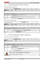
Fig. 20: Setting the register values: max. current difference, tripping class, measuring cycle time
Max. current difference
(
)
Default 5 A
Specification of the maximum permitted current difference between the L1, L2 and L3
phases.
Tripping class
(
Default: 10 s
Specification of the tripping class.
Measuretime
(
Default: 50 ms
Specification of the measuring cycle time.
Summary of Contents for KL8001
Page 2: ......
Page 4: ...Table of contents KL8001 and KL9060 4 Version 2 0 0...

