Product overview
KL3403
14
Version: 3.1.0
2.3
Basic function principles
Measuring principle
The KL3403 works with 6 analog/digital converters for recording the current and voltage values of all
3 phases. The values are sampled with a time grid of approximately 16 µs.
Recording and processing is synchronous and identical for the 3 phases. The signal processing for one
phase is described below. This description applies correspondingly for all 3 phases. The total power and the
total energy consumption represent the sum of the 3 phases, the mean current represents the average.
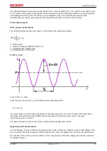
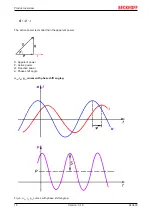
Voltage u and current i curves
Fig. 4: Voltage u and current i curves
RMS value calculation
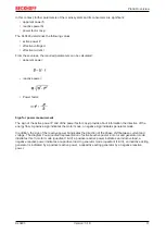
The rms value for voltage and current is calculated over a measuring interval, in this case the period T. The
following equations are used:
u
(t)
: instantaneous voltage value
i
(t)
: instantaneous current value
n: number of measured values
For a measurement in a 50 Hz mains system (period T = 20 ms), 1280 measured values are considered
within a calculation.
Measuring interval
The choice of the right measuring interval is important for the quality of the measurement. The measuring
interval must be at least ¼ T. ¼ T, ½ T, T end multiples of ½ T are sensible values. If a random interval is
used that does not correspond to a multiple of ½ T and is significantly less than 5 T, the measured value will
fluctuate significantly.

