background image

Foreword

KL3208, KL3228/KS3228

9

Version: 3.3.0

1.4

Beckhoff Identification Code (BIC)

The Beckhoff Identification Code (BIC) is increasingly being applied to Beckhoff products to uniquely identify
the product. The BIC is represented as a Data Matrix Code (DMC, code scheme ECC200), the content is
based on the ANSI standard MH10.8.2-2016.

Fig. 1: BIC as data matrix code (DMC, code scheme ECC200)

The BIC will be introduced step by step across all product groups.

Depending on the product, it can be found in the following places:

• on the packaging unit

• directly on the product (if space suffices)

• on the packaging unit and the product

The BIC is machine-readable and contains information that can also be used by the customer for handling
and product management.

Each piece of information can be uniquely identified using the so-called data identifier
(ANSI MH10.8.2-2016). The data identifier is followed by a character string. Both together have a maximum
length according to the table below. If the information is shorter, spaces are added to it. The data under
positions 1 to 4 are always available.

The following information is contained:

Summary of Contents for KL3208

Page 1: ...Documentation EN KL3208 KL3228 KS3228 Eight channel input terminals for PT1000 NI1000 NTC 2021 08 12 Version 3 3 0...

Page 2: ......

Page 3: ...the Bus Terminal Block 25 3 6 ATEX Special conditions standard temperature range 27 3 7 ATEX Special conditions extended temperature range 28 3 8 Continuative documentation for ATEX and IECEx 29 3 9...

Page 4: ...Table of contents KL3208 KL3228 KS3228 4 Version 3 3 0 7 Appendix 53 7 1 Support and Service 53...

Page 5: ...n of products that have already been supplied may be made on the basis of the data diagrams and descriptions in this documentation Trademarks Beckhoff TwinCAT TwinCAT BSD TC BSD EtherCAT EtherCAT G Et...

Page 6: ...for trained specialists in control automation and drive engineering who are familiar with the applicable national standards Description of instructions In this documentation the following instruction...

Page 7: ...nical data updated Installation instructions for enhanced mechanical load capacity added Chapter TwinCAT including Link to FB_KL3208Config and FB_KL3228Config added Chapter ATEX Special conditions rep...

Page 8: ...3C 01 2 0 1 1A 00 3C 00 2 0 0 1A 00 3C 00 1 1 0 3B 00 1 0 0 3B 00 0 5 3A 00 The firmware and hardware versions delivery state can be taken from the serial number printed on the side of the terminal S...

Page 9: ...on the product it can be found in the following places on the packaging unit directly on the product if space suffices on the packaging unit and the product The BIC is machine readable and contains i...

Page 10: ...and data identifiers are used by Beckhoff and serve internal processes Structure of the BIC Example of composite information from item 1 to 4 and 6 The data identifiers are marked in red for better d...

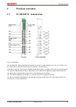
Page 11: ...ization over the entire freely selectable temperature range is realized with the aid of a microprocessor The bus terminals standard setting is Resolution 0 01 C within the temperature range of Ni1000...

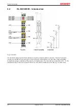
Page 12: ...eight resistance sensors The Bus Terminal s circuitry can handle sensors using the 1 wire technique Linearization over the entire freely selectable temperature range is realized with the aid of a micr...

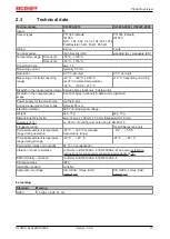
Page 13: ...ata words optional Power supply for the electronics via the K bus Current consumption from K bus typically 85 mA Electrical isolation 500 V K Bus signal voltage Weight app 75 g app 75 g Dimensions W x...

Page 14: ...ontact with highly insulating materials synthetic fibers plastic film etc Surroundings working place packaging and personnel should by grounded probably when handling with the devices Each assembly mu...

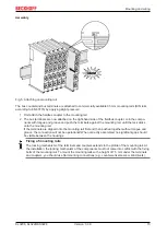
Page 15: ...til the lock clicks onto the mounting rail If the terminals are clipped onto the mounting rail first and then pushed together without tongue and groove the connection will not be operational When corr...

Page 16: ...components The six spring contacts of the K Bus E Bus deal with the transfer of the data and the supply of the Bus Terminal electronics The power contacts deal with the supply for the field electroni...

Page 17: ...tion testing or to damage on the terminal e g disruptive discharge to the PE line during insulation testing of a consumer with a nominal voltage of 230 V For insulation testing disconnect the PE suppl...

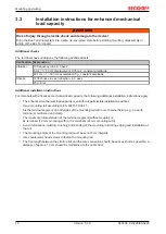
Page 18: ...hanical load capacity the following additional installation instructions apply The enhanced mechanical load capacity is valid for all permissible installation positions Use a mounting rail according t...

Page 19: ...ging density Standard wiring ELxxxx KLxxxx Fig 8 Standard wiring The terminals of ELxxxx and KLxxxx series have been tried and tested for years They feature integrated screwless spring force technolog...

Page 20: ...minals The terminals from these series with 16 terminal points are distinguished by a particularly compact design as the packaging density is twice as large as that of the standard 12 mm bus terminals...

Page 21: ...ely don t toggle 2 The wire can now be inserted into the round terminal opening without any force 3 The terminal point closes automatically when the pressure is released holding the wire securely and...

Page 22: ...1 5 mm2 Wire size width fine wire conductors 0 25 1 5 mm2 Wire size width conductors with a wire end sleeve 0 14 0 75 mm2 Wire size width ultrasonically bonded conductors only 1 5 mm2 Wire stripping l...

Page 23: ...el 1 R2 2 PT sensor channel 2 R3 3 PT sensor channel 3 R4 4 PT sensor channel 4 R5 5 PT sensor channel 5 R6 6 PT sensor channel 6 R7 7 PT sensor channel 7 R8 8 PT sensor channel 8 R1 9 PT sensor chann...

Page 24: ...via Power Contact 0 V back to the KL3228 Mount the KL3228 KL9187 directly before the KL9010 bus end terminal Mount the KL3228 KL9187 directly adjacent to each other and as far to the right as possible...

Page 25: ...ts between KL3228 and KL9187 This voltage drop can falsify the measured values of the KL3228 since the back wires of the PT sensors are also routed via the power contact 0 V Example for bad positionin...

Page 26: ...ent consumers are mounted to the right of KL3228 KL9187 Fig 15 KL3228 KL9187 Example for good positioning The current from the load resistors R1 and R2 does not flow back via the power contact marked...

Page 27: ...inst the rated operating voltage being exceeded by more than 40 due to short term interference voltages The individual terminals may only be unplugged or removed from the Bus Terminal system if the su...

Page 28: ...ct against the rated operating voltage being exceeded by more than 40 due to short term interference voltages The individual terminals may only be unplugged or removed from the Bus Terminal system if...

Page 29: ...al Systems Notes on the use of the Beckhoff terminal systems in hazardous areas according to ATEX and IECEx that is available for download on the Beckhoff homepage www beckhoff com 3 9 Disposal Produc...

Page 30: ...Fieldbus Box Modules can be prepared before the commissioning phase Later on this configuration can be transferred to the terminal station in the commissioning phase by means of a download For documen...

Page 31: ...the output image for commissioning of the output modules All possibilities in the online mode can be used in parallel with the actual fieldbus mode of the terminal station The fieldbus protocol alway...

Page 32: ...hand KS2000 window displays the terminals of the fieldbus station in a tree structure The right hand KS2000 window contains a graphic display of the fieldbus station terminals In the tree structure o...

Page 33: ...tree branch for KL3228 0000 For the KL3214 the branches Register Settings and ProcData are displayed Register enables direct access to the KL3228 registers A dialog mask for the parameterization of th...

Page 34: ...te the user scaling enUsrScale R32 0 43 and the manufacturer scaling enManScale R32 1 43 or disable the channel completely disChannel R32 11 43 Resistance thermometer sensor type Here you can set the...

Page 35: ...racteristic curve NI1000 with Landis Staefa characteristic curve 1500 100 C 4 5 Sample program for KL register communication via EtherCAT on KL3314 exemplary Using the sample programs This document co...

Page 36: ...and gain R33 R34 similar as per KS2000 Fig 21 Settings of KL3314 via visualisation of TwinCAT 3 At least following configuration setup shall be present coupler e g BK1120 or embedded PC KL3314 KL9010...

Page 37: ...n for the EtherCAT configuration of the example Checking NetId the EtherCAT tab of the EtherCAT device shows the configured NetId The first 4 numbers have to be identical with the project NetId of the...

Page 38: ...0 Byte SB6 39 CB6 39 16 22 Word DataIN6 DataOUT6 18 24 Byte SB7 39 CB7 39 19 26 Word DataIN7 DataOUT7 21 28 Byte SB8 39 CB8 39 22 30 Word DataIN8 DataOUT8 The terminal is represented in the compact pr...

Page 39: ...bin reserved CB1 5 Cali 1bin Terminal compensation function is activated A gain and offset calibration of the terminal can be carried out with the control byte in process data mode The code word must...

Page 40: ...0bin Read access 1bin Write access CB1 5 to CB1 0 Reg no Register number Enter the number of the register 41 that you want to read with input data word DataIn 38 or want to write with output data wor...

Page 41: ...Manufacturer scaling Offset 0x0000 0dec R W SEEPROM R20 43 Manufacturer scaling Gain 0x0100 256dec R W SEEPROM R21 Offset register two wire connection method specific specific R W SEEPROM R22 R28 res...

Page 42: ...d R8 Terminal description The terminal identifier is contained in register R8 KL3208 0010 0x0C88 3208dec KL3228 0000 0x0C9C 3228dec R9 Firmware version Register R9 contains the ASCII coding of the ter...

Page 43: ...er contains the reference value of the calibration which is determined during the vendor calibration R31 Code word register If you write values into the user registers without first entering the user...

Page 44: ...ser scaling User scaling can be activated in the feature register via bit R32 0 43 R34 User scaling gain This register contains the gain of the user scaling User scaling can be activated in the featur...

Page 45: ...k 0x00FF 255dec user defined NTC Avoid the mixed operation of low resistance PT NI sensors and high resistance NTC sensors on one terminal Due to large differences in the resistances of the sensor ty...

Page 46: ...control byte as a receipt in the status byte The terminal returns the firmware version 0x3341 in the input data word byte 1 and byte 2 This is to be interpreted as an ASCII code ASCII code 0x33 repre...

Page 47: ...ication switched on Bit 0 6 not set means reading the register Bits 0 5 to 0 0 specify the register number 31 with 01 1111bin The output data word byte 1 and byte 2 has no meaning during read access I...

Page 48: ...egister Output Data Byte 0 Control byte Byte 1 DataOUT1 high byte Byte 2 DataOUT1 low byte 0xA0 1010 0000bin 0xXX 0xXX Explanation Bit 0 7 set means Register communication switched on Bit 0 6 not set...

Page 49: ...1 DataIN1 high byte Byte 2 DataIN1 low byte 0x9F 1001 1111bin 0xXX 0xXX Explanation The terminal returns a value as a receipt in the status byte that differs only in bit 0 6 from the value of the cont...

Page 50: ...nts for programming diagnosis and configuration Any Windows programs for instance visualization programs or Office programs can access TwinCAT data via Microsoft interfaces or can execute commands A p...

Page 51: ...s A message router manages and distributes all the messages both in the system and via TCP IP connections PC systems can be connected to one another by TCP IP Bus Terminal controllers are connected vi...

Page 52: ...more detailed description can be found in the Beckhoff Information System FB_KL3208Config TwinCAT2 TwinCAT PLC Lib I O functions Bus Terminal configuration TwinCAT3 TwinCAT 3 PLC Lib Tc2_I O functions...

Page 53: ...components there Beckhoff Support Support offers you comprehensive technical assistance helping you not only with the application of individual Beckhoff products but also with other wide ranging serv...

Page 54: ...cting a cable on a terminal point 21 Fig 12 KL3208 0010 Contact assignment 23 Fig 13 KL3228 0000 Contact assignment 24 Fig 14 KL3228 KL9187 Example for bad positioning 25 Fig 15 KL3228 KL9187 Example...

Page 55: ......

Page 56: ...Beckhoff Automation GmbH Co KG H lshorstweg 20 33415 Verl Germany Phone 49 5246 9630 info beckhoff com www beckhoff com More Information www beckhoff com KL3xxx...

Reviews: