background image

Mounting and wiring

KL304x, KL305x

15

Version: 4.0

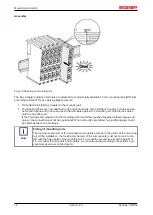
Disassembly

Fig. 7: Disassembling of terminal

Each terminal is secured by a lock on the mounting rail, which must be released for disassembly:

1. Pull the terminal by its orange-colored lugs approximately 1 cm away from the mounting rail. In doing

so for this terminal the mounting rail lock is released automatically and you can pull the terminal out of
the bus terminal block easily without excessive force.

2. Grasp the released terminal with thumb and index finger simultaneous at the upper and lower grooved

housing surfaces and pull the terminal out of the bus terminal block.

Connections within a bus terminal block

The electric connections between the Bus Coupler and the Bus Terminals are automatically realized by
joining the components:

• The six spring contacts of the K-Bus/E-Bus deal with the transfer of the data and the supply of the Bus

Terminal electronics.

• The power contacts deal with the supply for the field electronics and thus represent a supply rail within

the bus terminal block. The power contacts are supplied via terminals on the Bus Coupler (up to 24 V)
or for higher voltages via power feed terminals.

Note

Power Contacts

During the design of a bus terminal block, the pin assignment of the individual Bus Termi-
nals must be taken account of, since some types (e.g. analog Bus Terminals or digital 4-
channel Bus Terminals) do not or not fully loop through the power contacts. Power Feed
Terminals (KL91xx, KL92xx or EL91xx, EL92xx) interrupt the power contacts and thus rep-
resent the start of a new supply rail.

PE power contact

The power contact labeled PE can be used as a protective earth. For safety reasons this contact mates first
when plugging together, and can ground short-circuit currents of up to 125 A.

Summary of Contents for KL304 Series

Page 1: ...Documentation KL304x KL305x Single Dual and Four Channel Analog Input Terminals Measuring range 0 20 mA and 4 20 mA Single ended 4 0 2017 10 06 Version Date...

Page 2: ......
Page 3: ...ED description 21 3 6 KL3042 KL3052 Connection and LED description 22 3 7 KL3044 KL3054 Connection and LED description 23 3 8 ATEX Special conditions standard temperature range 24 3 9 ATEX Special con...

Page 4: ...Table of contents KL304x KL305x 4 Version 4 0...

Page 5: ...the data diagrams and descriptions in this documentation Trademarks Beckhoff TwinCAT EtherCAT Safety over EtherCAT TwinSAFE XFC and XTS are registered trademarks of and licensed by Beckhoff Automatio...

Page 6: ...familiar with the applicable national standards Description of symbols In this documentation the following symbols are used with an accompanying safety instruction or note The safety instructions must...

Page 7: ...L3052 KL3054 FW HW FW HW FW HW FW HW FW HW FW HW 4 0 3C 08 3C 07 3B 04 3C 07 3C 07 3B 04 The firmware and hardware versions delivery state can be found in the serial number printed on the side of the...

Page 8: ...e from 0 mA to 20 mA The KL3051 terminal processes signals in the range from 4 mA to 20 mA The voltage for the sensors is supplied to the terminals via the power contacts The power contacts can option...

Page 9: ...mA to 20 mA The KL3052 terminal processes signals in the range from 4 mA to 20 mA The voltage for the sensors is supplied to the terminals via the power contacts The power contacts can optionally be s...

Page 10: ...to the automation device The KL3044 terminal processes signals in the range from 0 mA to 20 mA The KL3054 terminal processes signals in the range from 4 mA to 20 mA The input electronics is independe...

Page 11: ...60715 Permissible ambient tempera ture range during operation 0 C 55 C 25 C 60 C extended temperature range 0 C 55 C 25 C 60 C ex tended temperature range Permissible ambient tempera ture range durin...

Page 12: ...e calibration values takes place after each sampling of the analog signal This is followed by manufacturer and user scaling The process data that are transferred to the Bus Coupler are calculated usin...

Page 13: ...ntact with highly insulating materials synthetic fibers plastic film etc b Surroundings working place packaging and personnel should by grounded probably when handling with the devices c Each assembly...

Page 14: ...lock clicks onto the mounting rail If the Terminals are clipped onto the mounting rail first and then pushed together without tongue and groove the connection will not be operational When correctly as...

Page 15: ...ents The six spring contacts of the K Bus E Bus deal with the transfer of the data and the supply of the Bus Terminal electronics The power contacts deal with the supply for the field electronics and...

Page 16: ...on testing or to damage on the terminal e g disruptive discharge to the PE line during insulation testing of a consumer with a nominal voltage of 230 V For insulation testing disconnect the PE supply...

Page 17: ...ture e g an earth terminal or reinforced end clamp The maximum total extension of the terminal segment without coupler is 64 terminals 12 mm mounting with or 32 terminals 24 mm mounting with Avoid def...

Page 18: ...ctor from the top of the housing for servicing The lower section can be removed from the terminal block by pulling the unlocking tab Insert the new component and plug in the connector with the wiring...

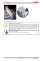
Page 19: ...tables concern ing the wire size width below 3 4 2 Wiring WARNING Risk of electric shock and damage of device Bring the bus terminal system into a safe powered down state before starting installation...

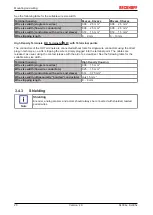
Page 20: ...ut tools for single wire conductors using the direct plug in technique i e after stripping the wire is simply plugged into the terminal point The cables are released as usual using the contact release...

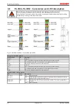
Page 21: ...nternally connected to terminal point 7 and negative power contact Shield 4 PE contact internally connected to terminal point 8 n c 5 not used 24 V 6 24 V internally connected to terminal point 2 and...

Page 22: ...nnected to terminal point 7 and negative power contact Shield 4 PE contact internally connected to terminal point 8 Input 2 5 Input 2 24 V 6 24 V internally connected to terminal point 2 and positive...

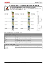
Page 23: ...54 Terminal point No Comment Input 1 1 Input 1 GND 2 Internal ground internally connected to terminal point 6 Input 3 3 Input 3 GND 4 Internal ground internally connected to terminal point 8 Input 2 5...

Page 24: ...against the rated operating voltage being exceeded by more than 40 due to short term interference voltages The individual terminals may only be unplugged or removed from the Bus Terminal sys tem if th...

Page 25: ...protect against the rated operating voltage being exceeded by more than 40 due to short term interference voltages The individual terminals may only be unplugged or removed from the Bus Terminal sys t...

Page 26: ...of the Beckhoff terminal systems in potentially explo sive areas ATEX Pay also attention to the continuative documentation Notes about operation of the Beckhoff terminal systems in potentially explosi...

Page 27: ...bus Box Modules can be prepared before the commissioning phase Later on this configuration can be transferred to the terminal station in the commissioning phase by means of a download For documentatio...

Page 28: ...ules directly online The same high level dialogs and register access are available for this purpose as in the configuration phase The KS2000 offers access to the process images of the bus couplers and...

Page 29: ...tatus byte is always mapped in addition to the data bytes This is always located in the low byte at the offset address of the terminal channel Fig 17 Mapping in the Lightbus coupler example for KL3042...

Page 30: ...onfiguration software can be used for parameterizations via the serial inter face of the Bus Coupler independent of the fieldbus system 5 2 Mapping in the Bus Coupler As already described in the Termi...

Page 31: ...yte Complete evaluation yes Motorola format yes Word alignment yes 0 Res Ch1 CB SB 1 Ch1 D0 Ch1 D1 2 3 Key Complete evaluation The terminal is mapped with control and status byte Motorola format Motor...

Page 32: ...t High byte Low byte Complete evaluation yes Motorola format yes Word alignment yes 0 Res Ch1 CB SB 1 Ch1 D0 Ch1 D1 2 Res Ch2 CB SB 3 Ch2 D0 Ch2 D1 Key Complete evaluation The terminal is mapped with...

Page 33: ...ation yes Motorola format no Word alignment yes 0 Res Ch1 CB SB 1 Ch1 D1 Ch1 D0 2 Res Ch2 CB SB 3 Ch2 D1 Ch2 D0 4 Res Ch3 CB SB 5 Ch3 D1 Ch3 D0 6 Res Ch4 CB SB 7 Ch4 D1 Ch4 D0 Conditions Word offset H...

Page 34: ...ariable R W RAM R16 36 Hardware version number 0x R W SEEROM R17 36 Hardware compensation Offset specific R W SEEROM R18 36 Hardware compensation Gain specific R W SEEROM R19 36 Manufacturer scaling O...

Page 35: ...iplexed shift registers and their length in bits The Bus Coupler sees this structure R11 Signal channels Related to R10 this contains the number of channels that are logically present Thus for example...

Page 36: ...manufacturer s equation of the straight line Eq 1 3 12 The straight line equation is activated via register R32 37 1 corresponds to register value 0x0400 R21 Over range limit OVRL 16 bits signed inte...

Page 37: ...tive 0 For filter properties see R37 38 Bits 12 to 15 Reserved don t change If the Siemens output format is selected the lowest three bits are used for status evaluation The process data is represente...

Page 38: ...st order IIR filter cut off frequency fg approx 1 kHz The implemented IIR filters do not have any notch behavior i e they do not explicitly suppress any frequency 0x0200 1st order IIR filter cut off f...

Page 39: ...scription Bit 7 0bin Bit 6 1bin Terminal compensation function is enabled Bit 5 reserved Bit 4 1bin Gain calibration Bit 3 1bin Offset calibration Bit 2 0bin slower cycle 1000 ms 1bin fast cycle 50 ms...

Page 40: ...e once the status byte in the input process image has returned an acknowledgment see example Bit 0 to 5 Address The address of the register to be addressed is entered in bits 0 to 5 of the control byt...

Page 41: ...2 0x35 0xXX 0xDF the code word 36 is set and the terminal returns the register address with bit 7 for register access as acknowledgment Byte Byte 3 Byte 2 Byte 1 Byte 0 Name DataIN 1 DataIN 0 Not used...

Page 42: ...byte Byte 2 DataOUT1 low byte 0xDF 1101 1111bin 0x12 0x35 Explanation Bit 0 7 set means Register communication switched on Bit 0 6 set means writing to the register Bits 0 5 to 0 0 specify the regist...

Page 43: ...xample The bits of the feature register change the properties of the terminal and have a different meaning depending on the type of terminal Refer to the description of the feature register of your te...

Page 44: ...taOUT1 low byte 0xDF 1101 1111bin 0x00 0x00 Explanation Bit 0 7 set means Register communication switched on Bit 0 6 set means writing to the register Bits 0 5 to 0 0 specify the register number 31 wi...

Page 45: ...off components there Beckhoff Headquarters Beckhoff Automation GmbH Co KG Huelshorstweg 20 33415 Verl Germany Phone 49 0 5246 963 0 Fax 49 0 5246 963 198 e mail info beckhoff com Beckhoff Support Supp...

Page 46: ...ard wiring 18 Fig 10 Pluggable wiring 18 Fig 11 High Density Terminals 18 Fig 12 Connecting a cable on a terminal point 19 Fig 13 KL3041 KL3051 Connection and LEDs 21 Fig 14 KL3042 KL3052 Connection a...

Reviews: